2026 Professional CNC Machine Manufacture and Supplier from china:Jinan Senyo Machinery Co., Ltd


 +86 1525 3141 880

HOME >> Applications >> Industrial Applications >> Wood
From: 本站 Date: 02nd January 2025 Author: SENYOCNC Views: 1257

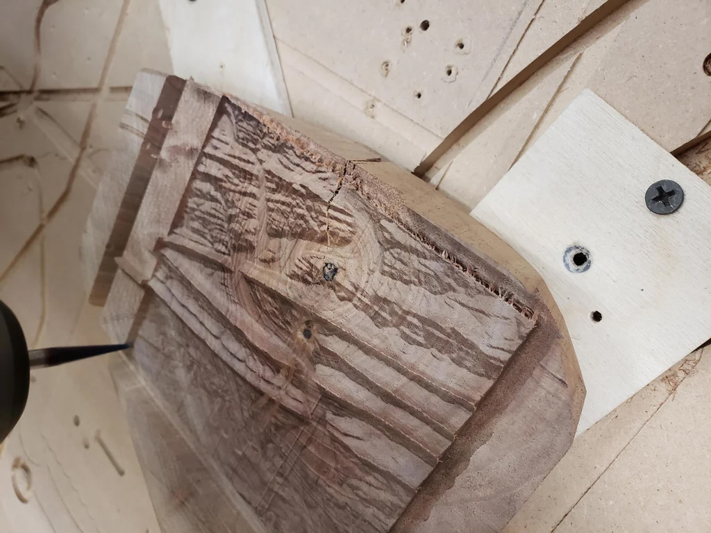
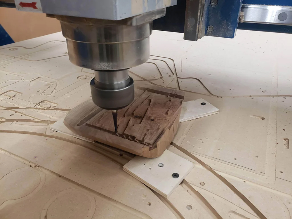
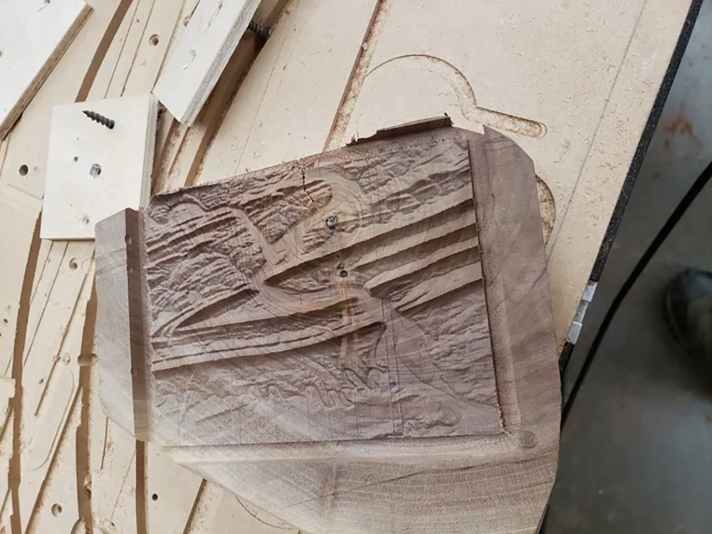


Autodesk Fusion 360
CNC Router
Scrap Walnut
1/4" Sharp 2 Flute Endmill
Amana 1/16 Tapered Ballnose Endmill P/N #46282-K
Scrap wood and 6 screws for workholding
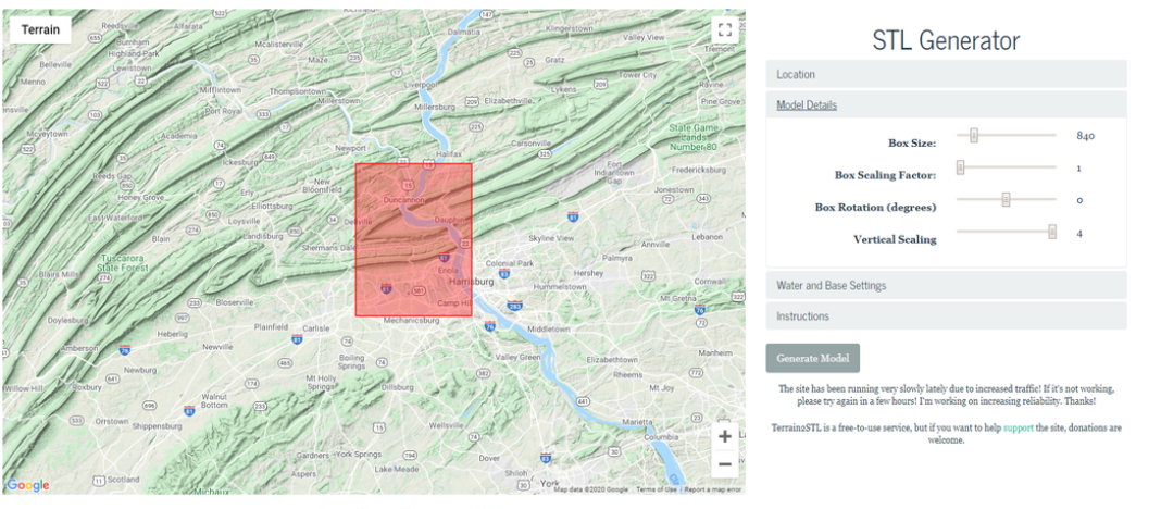
I wanted to cut a relief map
Search online for Terrain2STL or visit jthatch.com/Terrain2STL, pick your area and choose your settings.
Settings I used:
Box Size: 840 (I've tried larger ones in the past and my computer really struggled)
Box Scaling Factor: 1
Box Rotation: 0
Vertical Scaling: 4
I maxed out the vertical scaling to exaggerate the mountains.
Water and Base Settings:
Water Drop: 5
Base Height: 1 Again, I wanted to maximize the contrast in my mountains.
When you get everything just right, you are ready to click Generate Model. Take note of where you saved the file.
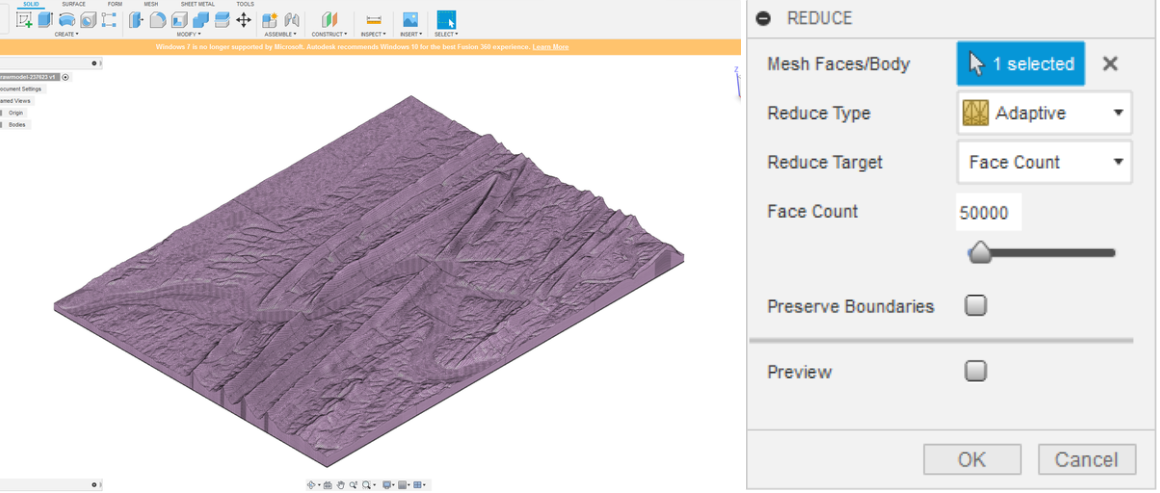
Open and extract your .stl model.
Click File --> Upload, and navigate to the location of your downloaded model.
Click the Show Data Panel at the very top left of the screen if your model doesn't load automatically.
When your .stl model is first uploaded into Fusion it should look like the Image 1 above.
This is comprised of thousands and thousands of 'faces' (over 260 thousand for my model).
In order to assign advanced toolpaths, we first need to convert it from a mesh of faces into a solid body.
First click the drop down under Bodies to display MeshBody1. Right click MeshBody1 and click Properties.
This should display a Facet Count among other info. To convert a mesh body into a solid body, Fusion 360 requires fewer than 50,000 facets.
Chances are that your model has much more than that, so we will need to reduce the number of faces.
Next navigate to the Mesh tab at the top of the program. The first thing we will need to do is select 'Make Closed Mesh' under the modify tab.
This is not always necessary, but I have run into trouble when converting the model if this step is skipped.
MeshBody1 should automatically be selected, if not click MeshBody1 under the Bodies folder on the left hand side.
I used a Rebuild Mode of Standard and a Density of 256.
You may want to reduce the density if your computer struggles to execute this command, but a low density may soften some of your scene's detail.
A new MeshBody should have been created, named MeshBody2.
Delete MeshBody1 to take some of the strain off your computer.
Next click the arrow beside Modify and select Reduce. Once again your model should automatically be selected,
if not make sure to select MeshBody2 from the left hand side. Use a Reduce Type of Adaptive,
and change Reduce Target to Face Count. Enter 50,000 or less for the target face count .
This will remove some detail from your model, but hopefully not too much.
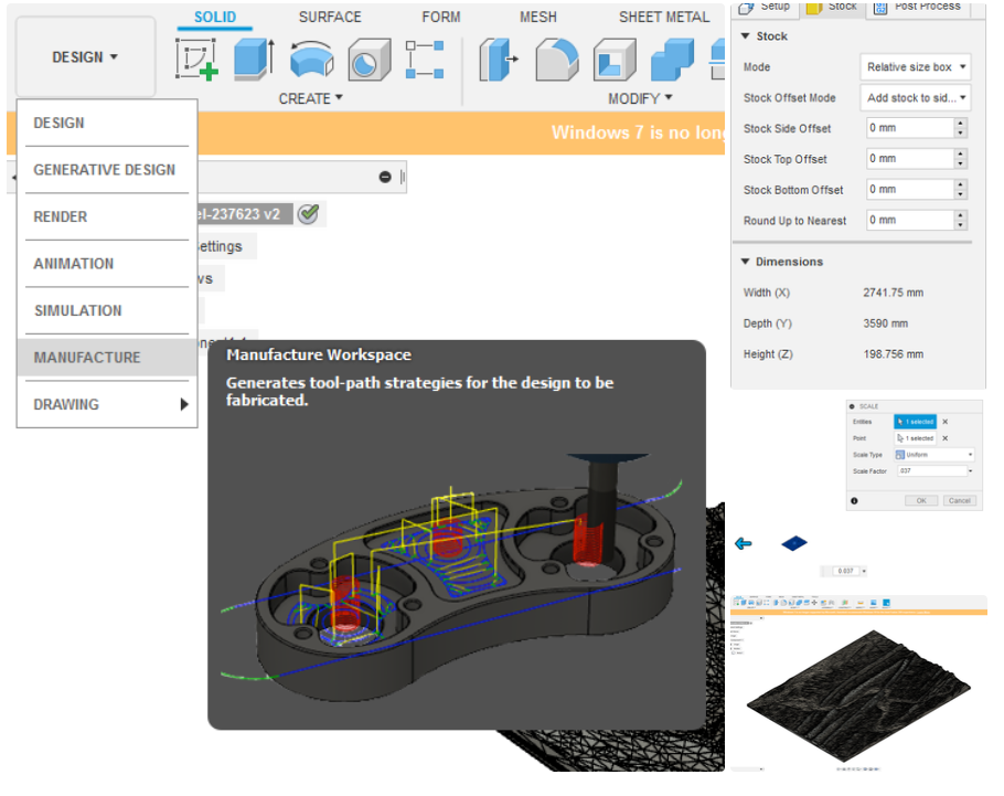
We now have a mesh model in 3D space, but no idea of how big it is in real terms.
First go to the Manufacture dropdown menu . Click the folder icon on the menu at the top above Setup.
We're just looking for the Dimensions here, so go to the Stock tab and record the dimensions at the bottom.
We will edit the rest later, so after you've written down the dimensions click OK.
My dimensions
X: 2741.75 mm
Y: 3590 mm
Z: 198.756 mm
No idea if that's a standard or not. Regardless, that is WAY bigger than the part I want to cut.
Decide on a length for your map. Choose one direction to 'drive' and the other will scale proportionally.
For example, I wanted the width of my scene to be 4 inches (101.6 mm).
Next return from the Manufacture workspace back to Design. Click the arrow beside Modify and select Scale from the drop down menu.
Select MeshBody2 from the design tree on the left. No need to select a point. Ensure Scale Type is Uniform
To calculate a shrinking Scale Factor, you need to divide your desired value (4 inches) by the current value.
Do the opposite if you need to enlarge the part. You can enter this directly into the scale factor dialog box. I input 101.6/2742.75.
We are now ready to convert the mesh into a body. Using the Solid tab at the top of the screen click the dropdown menu beside Modify,
place arrow over Mesh, and select Mesh to BRep. Select MeshBody2 from the design tree and select New Body.
You may get a message warning you that doing this may cause slow performance, but go ahead and click OK.
Congrats! We now have a model that Fusion 360 knows how to interact with. The color of your model should have changed from pinkish to greyish
This gives us the ability to assign advanced 3D toolpaths. You can now delete MeshBody2 to take some strain off your computer.
Step 4: Assign Toolpaths and Simulate
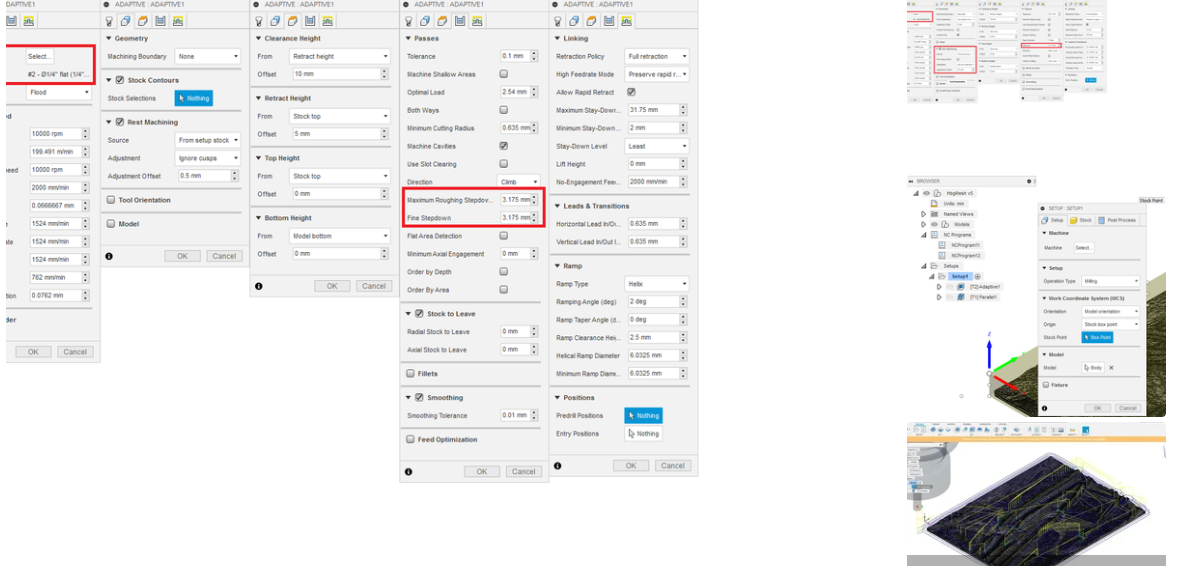
Return to the Manufacturing workspace.
Under 3D Toolpaths select Adaptive Clearing. Tool selection, RPM, and Feed Rates will vary greatly depending on your machine, material and workholding.
The above parameters are for cutting a 4" x 5.5" piece out of walnut with a 2 flute 1/4" sharp endmill.
After the adaptive clearing select the Parallel toolpath under the 3d menu. used a tapered ballnose endmill from Amana Tool Item #46282-K and the settings above
It's up to preference, but I found it was easiest to place my origin at the bottom left of the part.
The default origin is at the center of the part. If you'd like to change it right click Setup1 and select edit.
On the Setup tab select the bottom left corner of the stock using the stock point snap point.
Make sure that the Z level remains at the top of your stock
You can now simulate your toolpaths. If you click on one it should give you a preview of the cut path.
If you select both (hold shift) then click the simulate button at the top in the Actions menu you can do a simulation that includes the stock removal
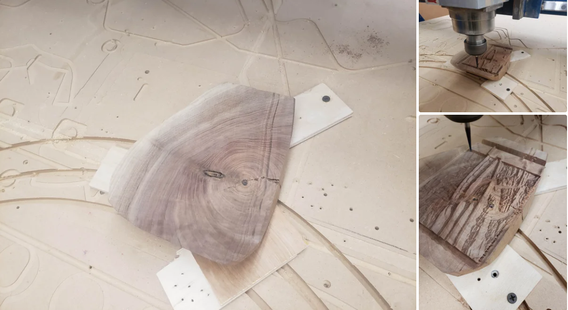
Chances are that you will not have the same type of CNC router,
To secure my part to the table, drilled 3 blind holes into the underside of my stock and used some short wood screws to attach a piece of scrap material.
then repeated the process on the other side of the scrap material and screwed them into the spoilboard.
Make sure the 3 pieces are the same thickness.
If you're having trouble securing your stock in a way that looks flat use a shim or consider adding a facing pass.
If you will not have any excess stock at the Z level, you will need to touch off your first tool to a known value, record Z,
and measure the offset from that value to the top of stock as your Z value.
For Example: Bring the tool down to 3 inches using a 123 block, and record the absolute Z value.
Then jog your tool down until it touches the top of the stock and record that absolute Z value.
Your Z offset will be the difference between those two values. Now when the top of your stock has been machined,
you can bring the second tool down to the 123 block and add that same offset.
Because the parallel toolpath takes such a small amount of material off, it is very important that the two tools are touched off on the same plane.
Once your X Y and Z are set, do a dry run.
If everything looks good you're ready to start making chips! Using a parallel toolpath like this takes a ton of time, but seems to be the most common method.
Step 6: Conclusion
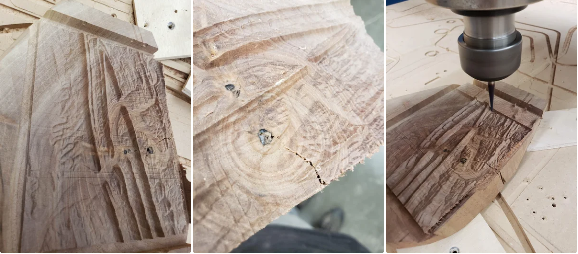
To http://jthatch.com/ for the awesome Terrain2STL tool.
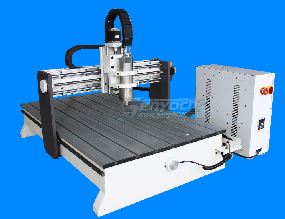
Mini Desktop CNC Router for Gifts Making Small Business
Best Granite marble manual polishing machine For Sale
Stone Processing CNC Equipment Automatic Tool Changer CNC Quartz Stone Machining
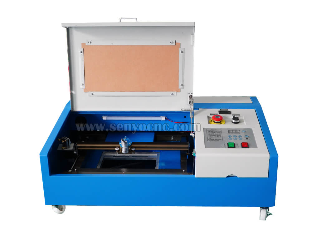
3020 40W Mini CO2 Laser Engraving Cutting Machine
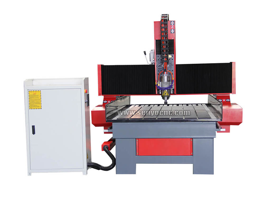
New Design Mini Stone CNC Machine for Marble, Granite and Quartz
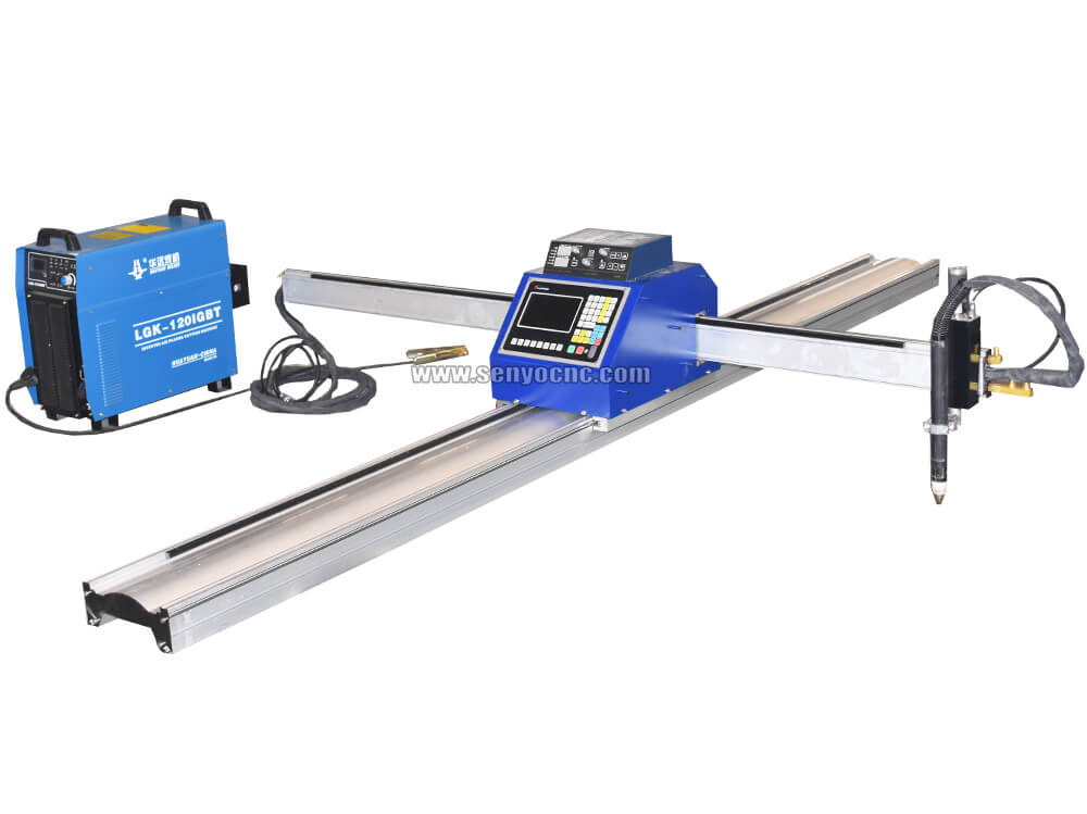
Portable CNC Flame Cutting Machine with Plasma Torch for Sale
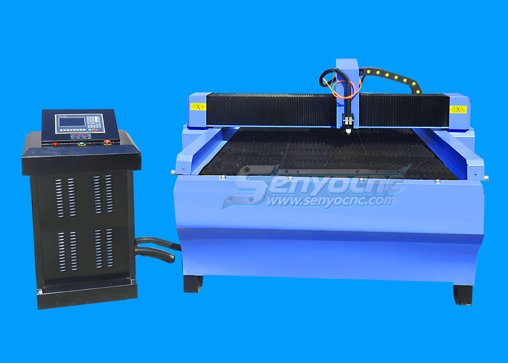
High-Precision Mini Hobby CNC Plasma Cutting Machine for Metal
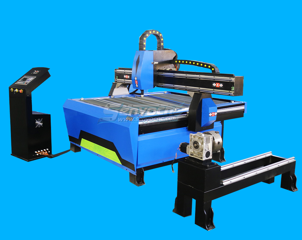
Mini CNC Plasma Cutter With Rotary
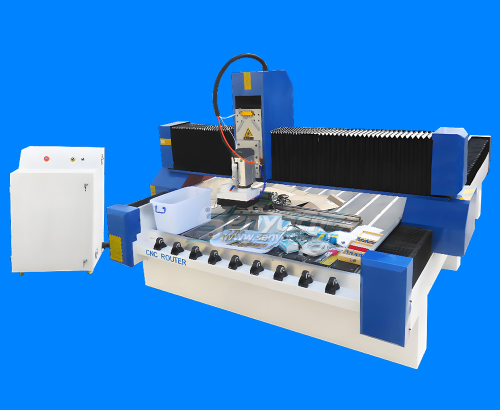
4 Axis 1325 Sculpture Machine Cnc Carving Marble Granite Stone Cnc Router
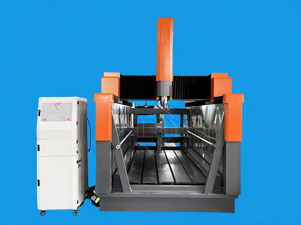
Z Height 1000MM 4-AXIS Stone Engraving CNC Machine Heavy-duty Stone CNC Machine Stone Relief Carving CNC For Sale
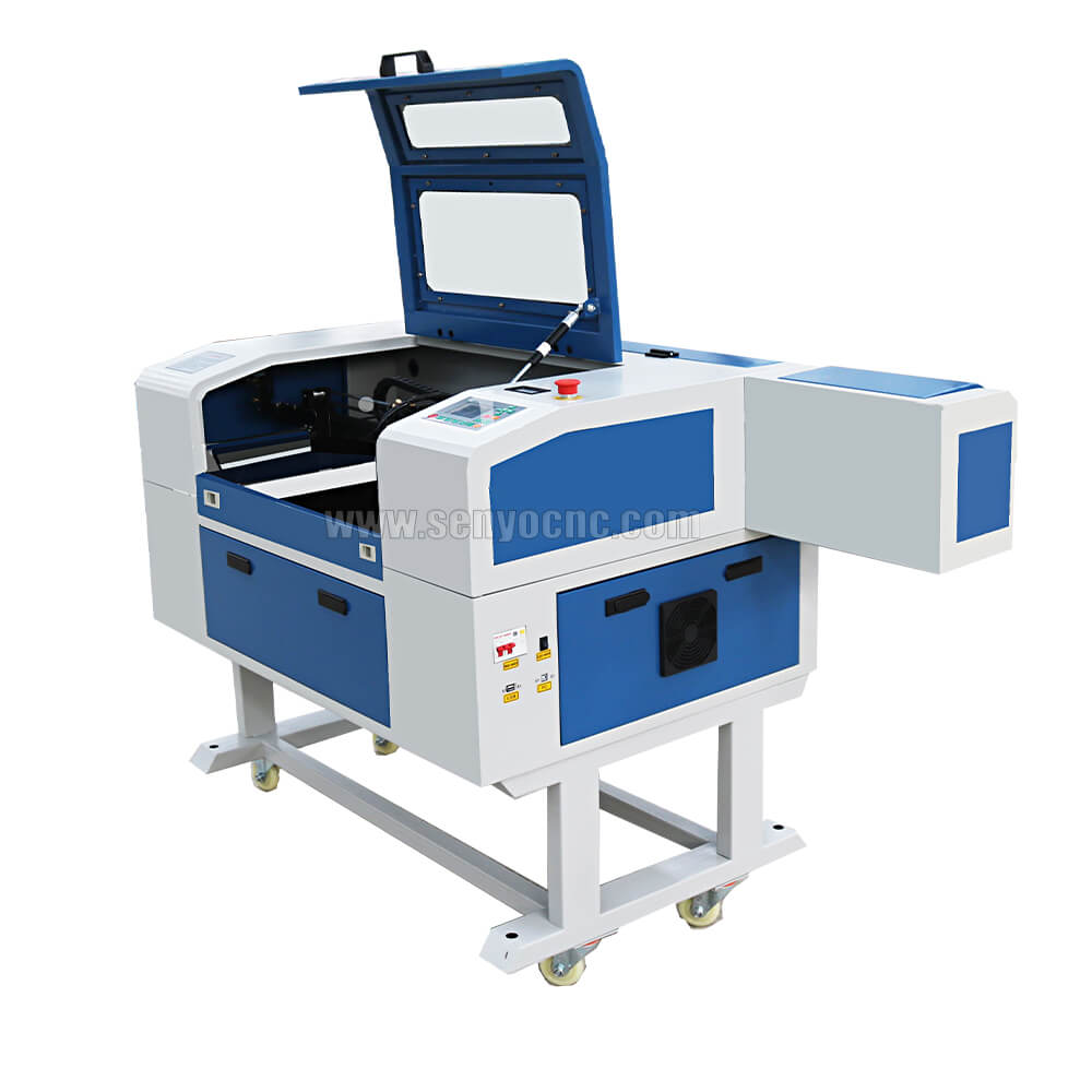
4030 portable mini co2 laser carving and desktop rubber stamp laser engraving machine
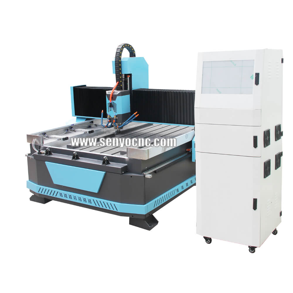
Stone CNC Router For Kitchen sink tile carving and cutting Marble, Granite and Quartz
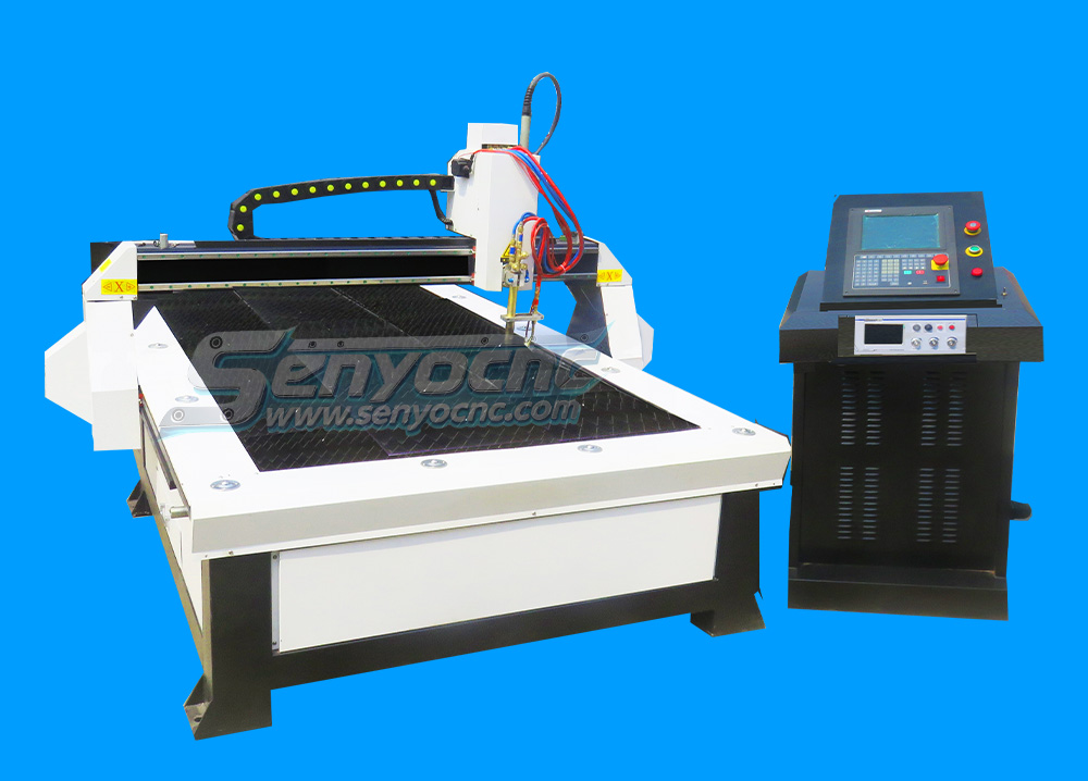
Robust CNC Plasma Cutting Machines with Flame Cut Head for Heavy-Duty Industrial Use
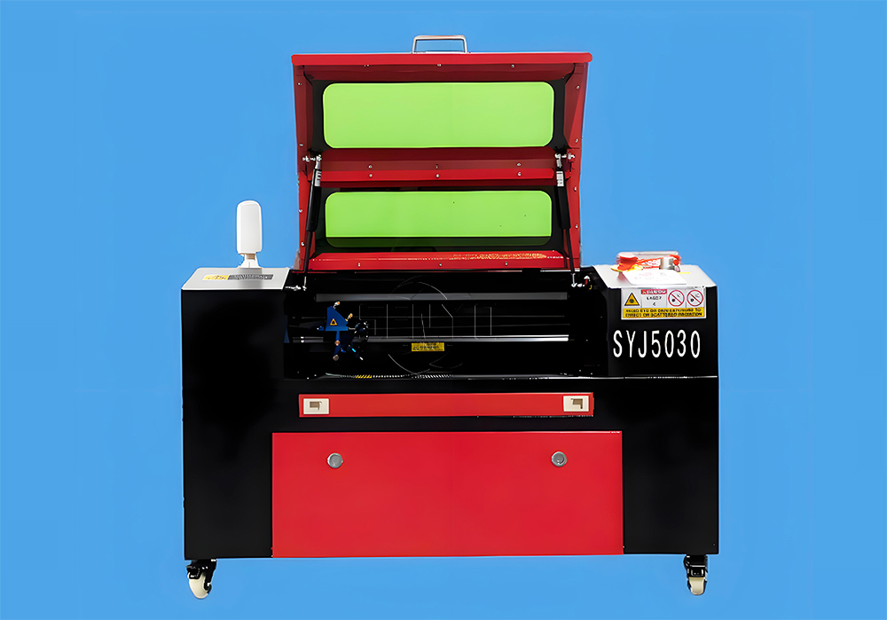
Small Portable CO₂ Laser Cutter Engraving for DIY & Business – Ideal for Wood, Acrylic, Leather
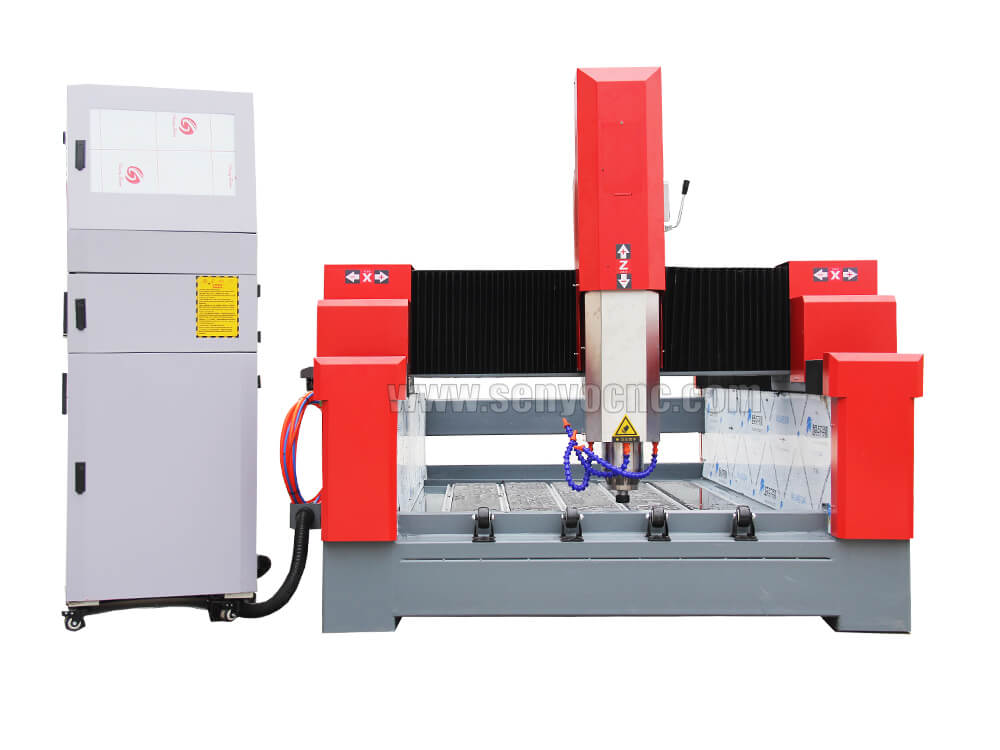
1325 3 Axis 4x8 CNC Stone Router for Sale
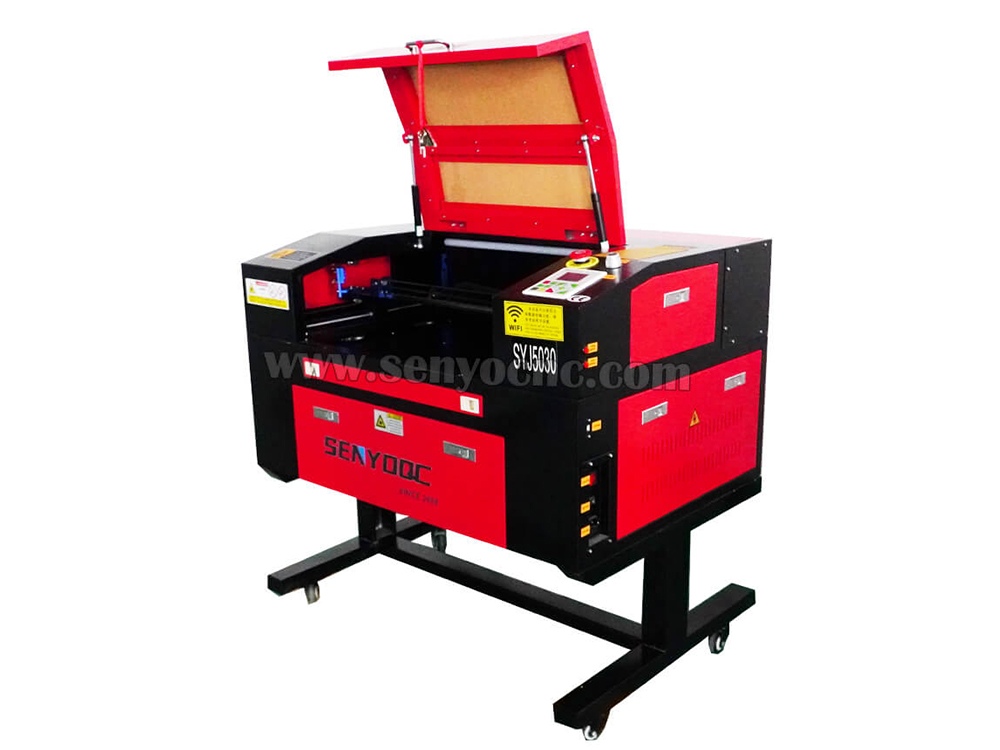
Mini CO2 Laser 5030 Cutting Engraving Machine For Sale
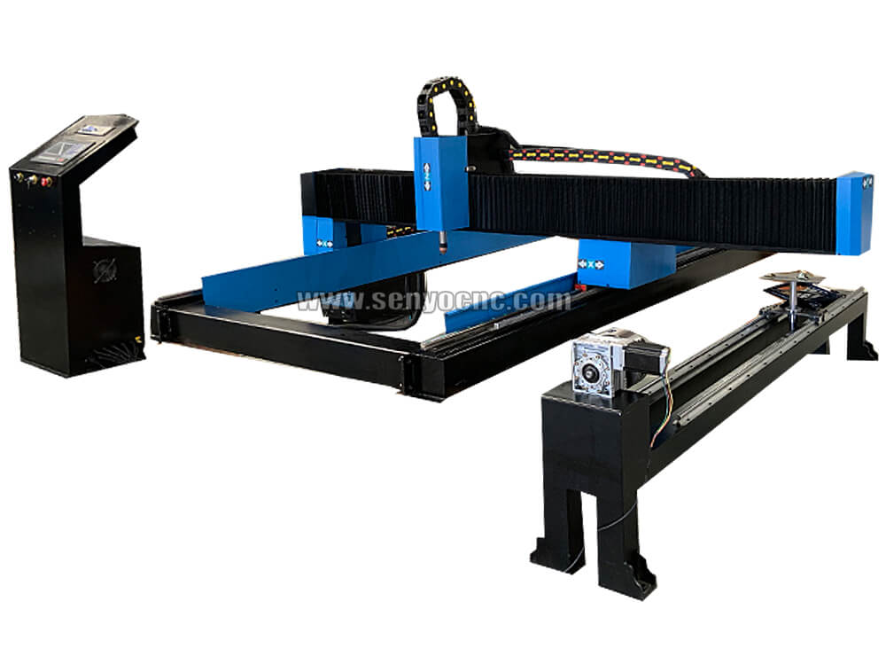
Portable CNC Plasma Flame Cutting Machine for Sale at Cost Price
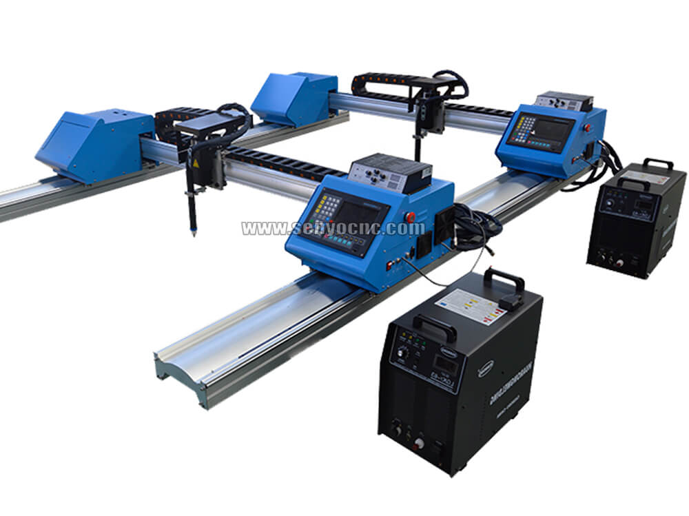
Portable Cnc Plasma Oxyfuel Sheet Metal Cutting Machine for sale
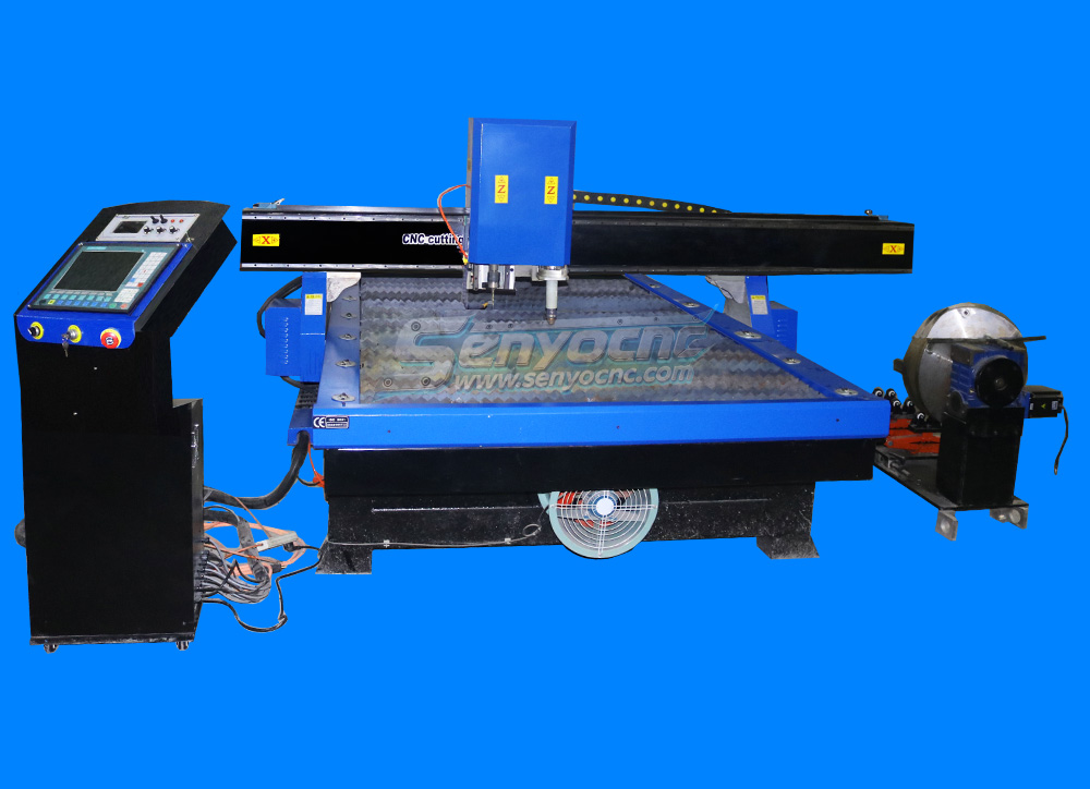
CNC Plasma Cutters for Customized Metalwork –Rotary&Drilling Head
Small Table design 6040 Easy Move CO2 Hobby Laser Cutter Machine for Beginners
High-Efficiency 2 Heads CNC Machine for Aluminum Stone Marble Engraving & Cutting
Best CNC 2 Spindle 4-AXIS Stone Carving Machine High-precision Stone Carving Stone Countertop Fabrication
Top Rated 2x3 CO2 Hobby Laser Cutting Machine for Sale at Affordable Price
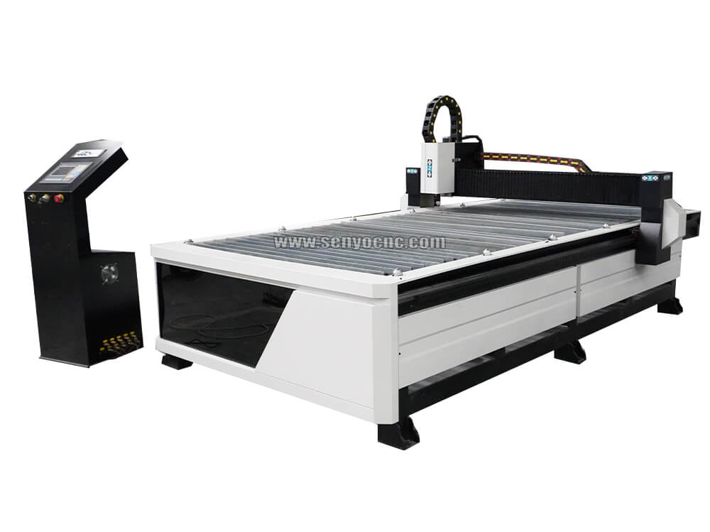
Best 4x8 CNC Plasma Cutter Table for Sale at Affordable Price
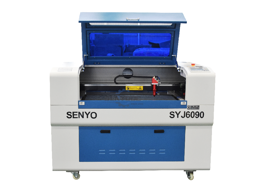
Entry Level CO2 Hobby Laser Cutter Machine for Beginners
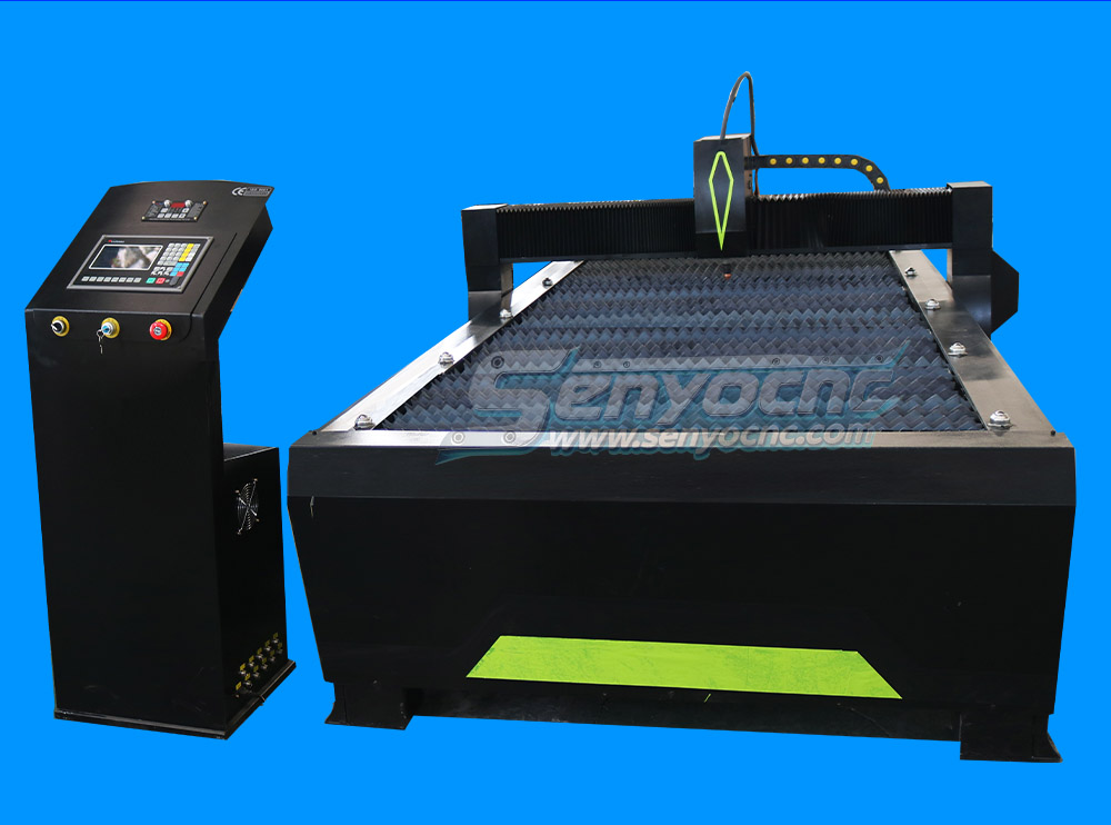
Top CNC Plasma Cutters for Automotive, Aerospace, and Manufacturing Industries
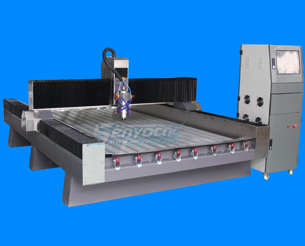
Precision Stone Engraving Machines for Memorials & Signs
Portable Co2 9060 Laser Nonmetal Cutting Engraving Machine
1090 CO2 Laser Machine with Ruida Controller for Non-metal Glass Acrylic Engraving Cutting
Entry Level 9060 CO2 Hobby Laser Cutter Machine for Beginners
The Apprentice Maze Puzzle Box
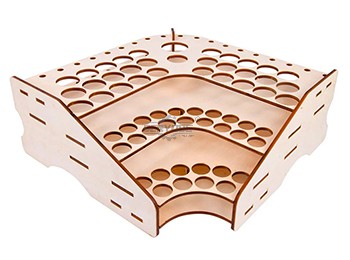
Box laser cutting software share
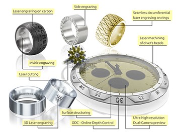
laser marking and engraving for the jewelry industry
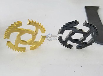
Copper cutting for fiber laser cutting machine
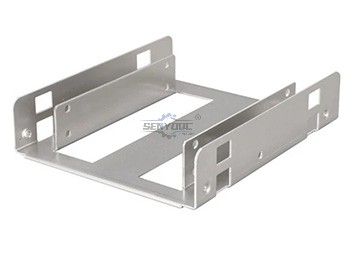
Aluminum Cutting for fiber laser cutting machine
CS Laser Cutting Factors that Affect the Process
Stainless steel Fiber Laser Cutting
2d&3d wood MDF carving and cutting
3D CNC Router for Stone Relief Carving Projects
Laser Cut Adjustable Table Lamp
CO2 Laser cutting Baby Birth Block
CO2 laser cutting and engraving for 6 Sided Box Puzzle
Co2 laser wood cut Illuminated Pattern Box
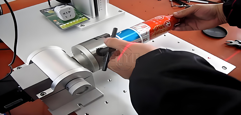
Engrave Round Parts With 50W Fiber Laser Marking Machine
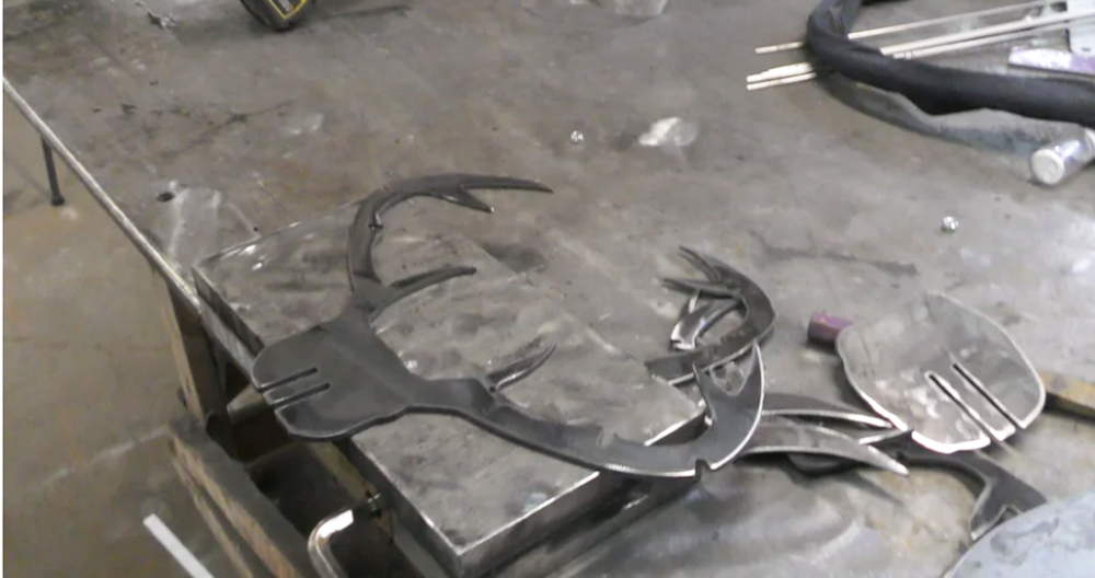
CNC Plasma Cut Deer Head
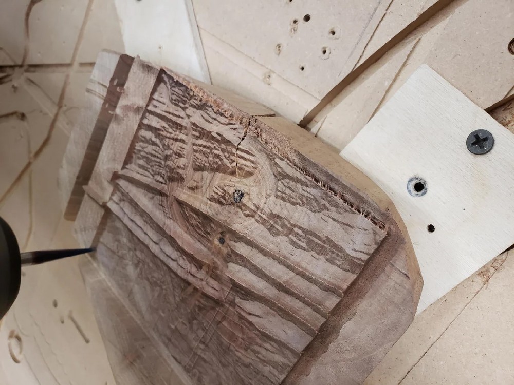
Relief Map on a CNC Router
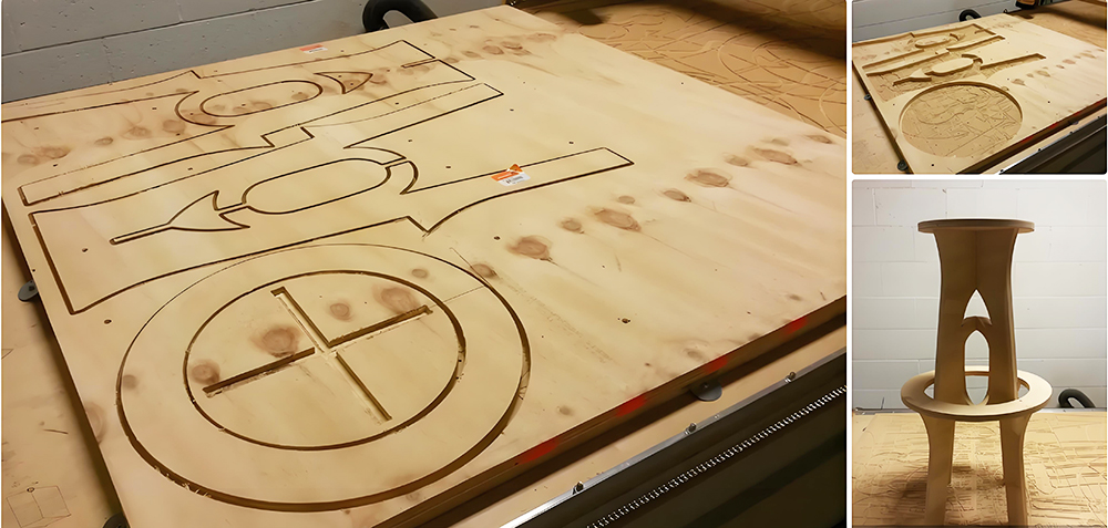
CNC Router Bar Stool
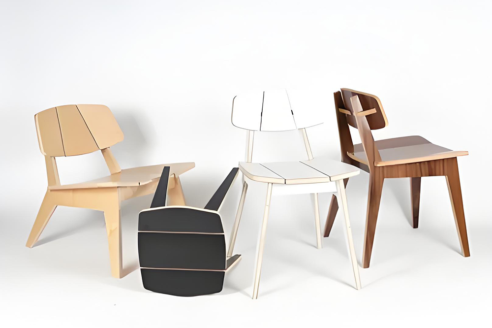
Wood Chair Made With CNC Router
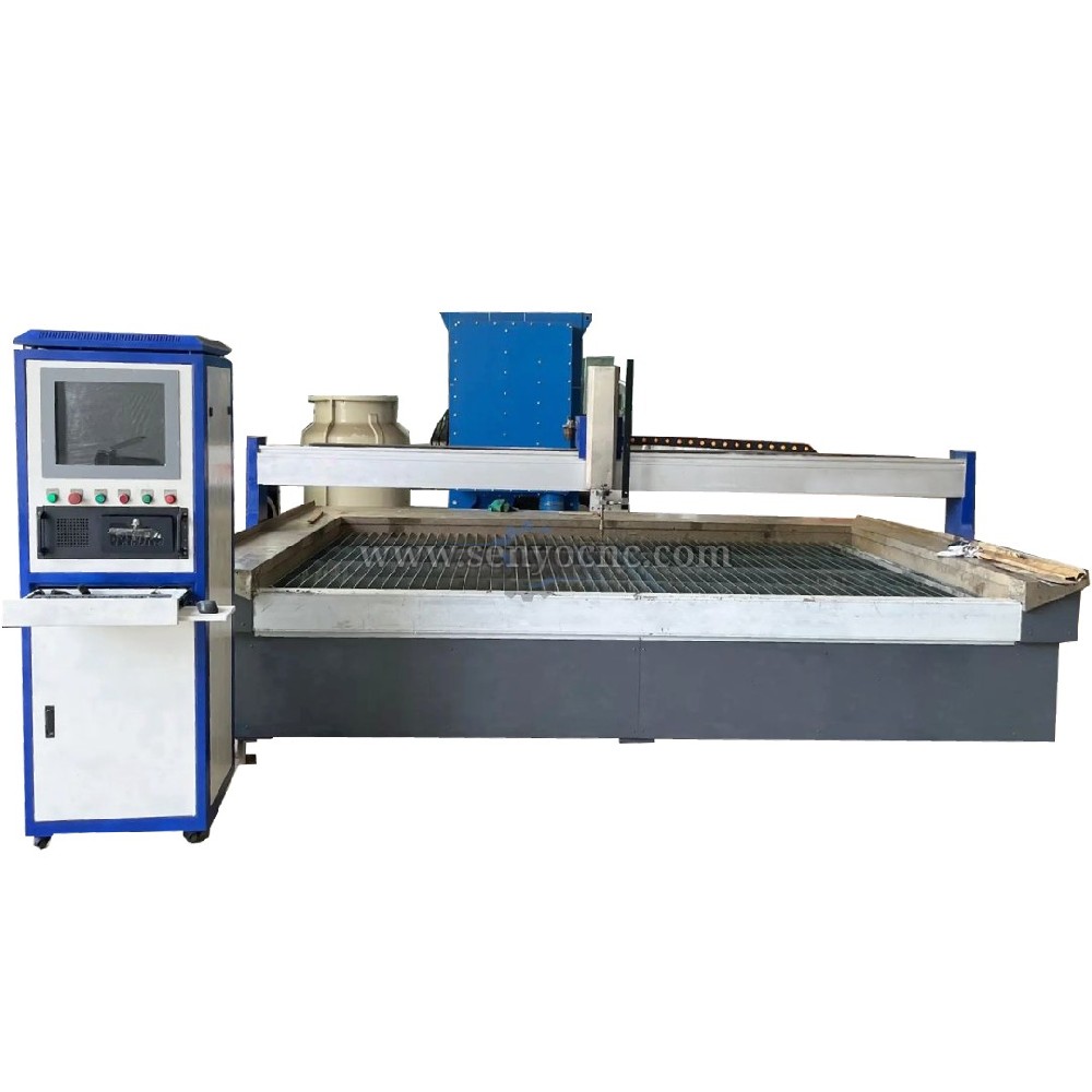
Competitive Price New Design Waterjet Machine 3 axis Cutting Machine

Typical industries that use waterjet technology
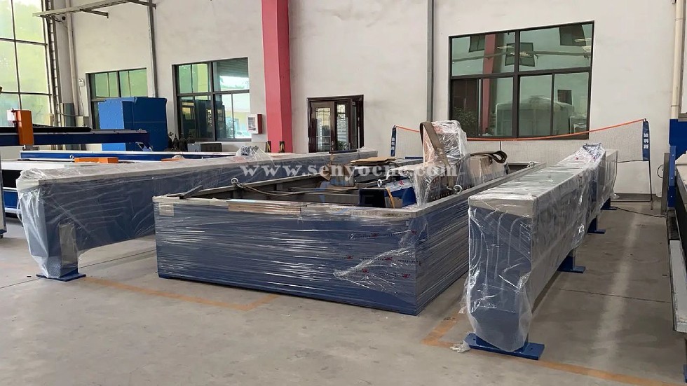
What main benefits to waterjet cutting ?

DTF Printer Machine Application
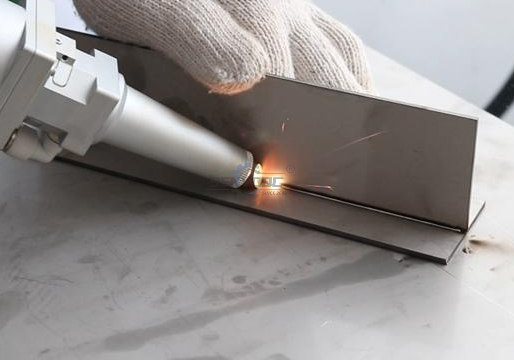
Typical fields of application
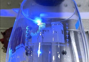
UV Laser Marking Machine For Glasses Engraving
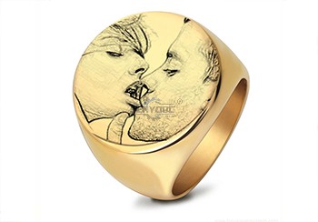
GOLD Engraving -Fiber laser marking work
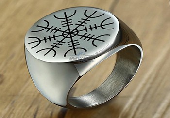
Sover Engraving -Fiber metal engraving and marking
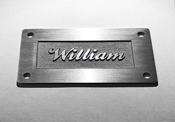
3D Marking Logo deep engraving -Fiber marking machine
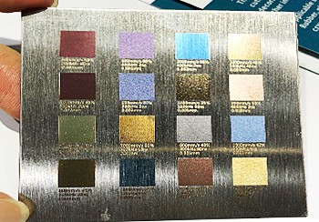
MOPA Fiber Laser Marking Machine Application and Samples
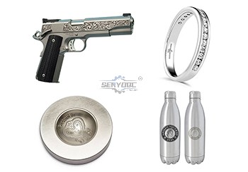
Fiber Laser Engraving and Marking Machine for Metalworking Projects
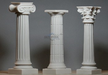
Stone shaft Rotary use engrave cnc router machine

Jacob from United States
I am a beginner at CNC, I’ve never used a CNC machine before and with in a day I was carving. An awesome machine for a beginner to learn as hobbyists. I used the manual and the help video. One hour to assemble and test, very friendly and easy to use. It’s a good buy for the money. I would definitely recommend this machine to someone getting into CNCs.
Weinstein from France
I've been using CNC plasma SYP2060-300A and I am very impressed with this unit.
This unit is of higher quality, made in China. Five stars all the way!
Stone Bridge Saw from 🇪🇸 Carlos García — Spain
Good choice for kitchen countertop fabrication. We can cut granite and marble accurately, including sink openings and straight cuts.Thank you Aillen
4 Axis Stone CNC Machine from 🇮🇹 Marco Rossi — Italy
We purchased this SYS1225-4Axis machine for stone columns and curved surfaces. The 4-axis function gives us much more flexibility.
Stone CNC Router from 🇫🇷 Pierre Martin — France
SYS2030 Very suitable for marble engraving and relief carving. The machine produces detailed patterns and the water cooling system works well.
Fiber Laser Marking Machine from 🇩🇪 Thomas Schneider — Germany
We use the SYJF-50W fiber laser for stainless steel and aluminum marking. The marking is precise and the software is convenient for daily production.
ATC CNC Router from 🇨🇦 Robert Miller — Canada
The SYM1325 ATC system works smoothly and makes production much faster. We use it for wood furniture and custom signage with very good results.
CNC Wood Router from 🇦🇺 James Carter — Australia
SYM1530 ATC Very good router for cabinet doors and furniture panels. The automatic tool changer saves a lot of working time during production.
🇬🇧 Daniel Wilson — UK CO2 Laser Cutting Machine from
SYJ1390-300W We mainly cut acrylic and MDF. The cutting edges are clean, and the machine is easy to operate. Very satisfied with SENYO’s support
SYS1530-2 Excellent machine for granite and marble engraving. from 🇺🇸 Michael Johnson — USA
The 4-axis function makes 3D carving much easier, and the machine frame feels very solida.


Jinan Senyo Machinery Co., Ltd

 manager@senyocnc.com
 SENYOCNC
 +86 1525 3141 880
 +86 1525 3141 880
 2061579344
