

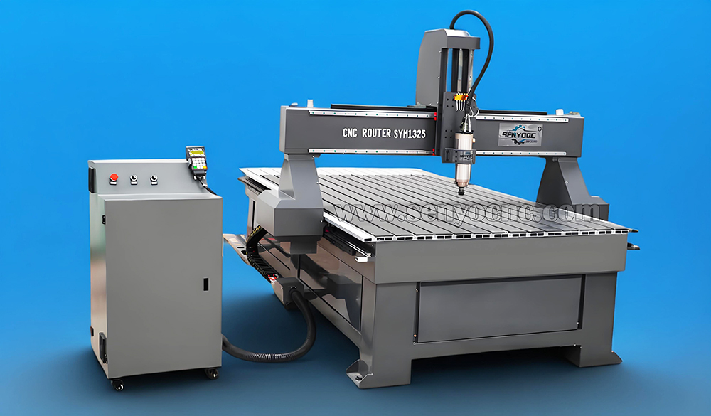
How to Install and Use NcStudio Controller & Software for CNC Router Machine?
From: 本站 Date: 12th March 2021 Author: admin Views: 7402
For safe operation and operation, please ground CNC router safely.
1. Grounding of CNC router machine body.
2. Grounding of control box of frequency converter.
Introduction of wiring of CNC router machine:
Rear ends of control box of CNC router machine connect with X and Y (two pieces), Z, frequency converter, limit
switch and external power source (AC 220V) separately. Front panel connects signal wire, another end of signal
wire connects control panel interface on the computer.
After finishing wiring of engraver, we start to install control software of engraver. (ARTCUT software, graphic and
text design software for engraver, has detailed description on its software, so no further introduction is made here).
After finishing software installation, insert PCI control card into PCI slot of the computer.
After placing control software into CD-ROM, operate SETUP. EXE file for installation, shown as following diagram:

Press NEXT to select installation catalogue.
After selecting installation catalogue, press NEXT.

Press NEXT.
Press NEXT.
Press NEXT until finishing installation. Then turn off the computer and insert PCI control card into PCI slot of the
computer. Start the computer again, the computer will automatically install driver program.
Introduction of Software
After the computer starts, start NC STUDIO from desktop of the computer, following interface will display.

How to Use NcStudio Controller?
Ncstudio TM interface consists of title bar, menu bar, tool bar, status bar and some function windows.
Operation modes and status
Operation mode
At any moment during user's operation on the machine, it is in one of following operation modes.
Automatic mode
Under automatic operation mode, machine movement functions by prior prepared processing program. Therefore,
the system shall be loaded processing program under automatic mode.
Jog mode
It is one of manual operation mode. Under jog mode, the user controls the machine by manual operation device, for
example, computer keyboard. When the user gives out movement signal by these devices, for example, press down
manual button, the machine continues movement until the signal disappears .
Increment mode
It is one of manual operation mode. Use computer keyboard to control the machine. The difference between jog
control mode and increment mode is the machine only moves defined distance by one pressing operation of the
user, i.e. from pressing to releasing. That is to say, the user can accurately control displacement of the machine by
increment mode.
Operation status
Each operation mode can be divided into several operation status, both operation modes and operation status
completely define the status of the machine.
ldle state
It is the most common state. Under this state, the machine hasn't any action output at present and is ready for
receiving new start and for starting new action.
L ocking state
Locking state is a kind of intemnal state and normally generates at state switchover, so the user can't contact it under
normal situations.
Operation state
When the machine is implementing any action, the system enters operation state.
Pause state
When the machine moves, if the user implements“operation | pause" command or the system receives MO1 (ready
command), then the system enters pause state and waits for further enter by the user, the user can continue to
implement by implementing“operation | start".
Function window is divided into three areas, including:
The first area: Digital control state window.
The second area: Processing locus, system log, program management, system parameter, programming and l/O
state window.
The third area: Automatic operation window and manual operation window.
Title bar
Title bar is on the topmost end of NcstudioTM software interface and is used for displaying software name and
loading processing program name, colors of title bar are used for indicating whether corresponding windows are
enabled.

Note:
In default setting of Windows, color of title bar of active window is blue; color of title bar of non-active window is
gray.

Digital control state window
Coordinate display window is at upper part of the screen and displays current position, feed speed and feed rate
adjustment of principal axis (cutting tool).
Processing status and time information
Title bar of digital control window also displays some state information. As shown in above diagram, for example,
during the system emulates, title bar displays“emulation mode" text, estimated implementation time (calculating by
100% feed rate) also displays at right side of title bar. During actual processing, actual processing time displays at
the right side.
Current position
For the convenience of describing various positions, Ncstudio TM displays two sets of coordinate systems of
mechanic coordinate system and work piece coordinate system at the same time.

The system supplies the method for convenient setting and revising base point of work piece. Set current point as
base point of work piece, that is to say, zero relative position of single axis. Move the cursor to coordinate display
area of this axis and click left key of mouse, then coordinate of this axis can become 0. If needing set all current
positions of three axes into 0, only need click in various coordinate areas.
Prompt:.
Another method for zeroing all work piece coordinates is to select the manual“operation (O) | setting current point
as work piece base point ()..." or to select equivalent tool bar button.
Feed speed
Various information such as setting speed, transient speed, speed scale factor and current line (paragraph) number
displays in feed speed area. Speed setting value and feed rate can be also revised.
| Feed rate slide bar: Dragging slide bar can adjust current movement speed within the range of 0~120%. Feed rate
displays in the form of percentage.
I Setting value. Setting value of feed speed is also the value given by parameter F in command G.
1 Actual value: Transient value of feed speed. It changes with setting value, current acceleration or deceleration
state and feed rate .
I Current line (paragraph) number: It displays paragraph number or line number of current implementation code.
When the system is at idle state, click setting value, and then speed setting dialog box pops up. When the system is
at automatic state, popup dialog box is used for setting default speed of automatic operation.
When the system is at manual state, popup dialog box is used for setting speed of manual operation, shown as
following diagram:

Automatic operation window
Automatic operation window displays current opening processing file. Ncstudio TM supports two processing program
formats of command G format and HP PLT fomat at present. The user can view current processing program by this
window.

Manual operation window
Manual window supplies an interactive operation environment for controlling machine by manual way to the user.
Since manual window is at function window area of main window, the method for the user to switchover several
windows and to activate manual window is:
Manual button area in this window includes six manual buttons that correspond to positive and negative directions
of axes X, Y and Z respectively.
Manual operation of the machine has two ways. Continuous jog way and increment stepping way that are
respectively introduced as following:
Continuous jog way.
Under continuous jog way, when manual window is current active window, press corresponding numerical key on
the keypad. When the key is at pressing state, the machine acts; when the key is released, the machine stops
action.
When implementing jog action, track window displays track locus by color of command G0O.
Increment stepping way.
It is similar to manual way. The difference between continuous jog way and increment stepping way is increment
stepping way can accurately control feed speed of machine kinematical axis.
The user can implement increment stepping operation by mouse and keyboard through interactive interface and
can also implement this operation by manual operation panel or operation box. Touching manual button every time
can correspond to given step length of axis movement.
Keyboard way.
When jog window is current active window, increasing or decreasing jog step length by direction key can see
change of jog step length button.
Mouse way.
Directly use mouse to click suitable step length button.
Note:
Avoid setting too large jog step length so as not to damage the machine by misoperation.
Mouse way.
Use left key of mouse to click the button, then the button is triggered once.
Note:
Since implementing jog command by the system each time needs certain time, so too frequent clicking may cause
the system to prompt error information that‘equipment is busy and current operation is invalid".
Increase/decrease depth.
Using +/-keys on the keypad and digital keys can quickly increase and decrease depth.
System parameter window
System parameters include two types: Processing parameters and producer parameters.
Their various parameters are explained in detail as following.
1. Processing parameters
Ncstudio TM processing parameters are set as following:
Manual speed: It includes manual high speed and manual low speed. These two values are used for movement
speed under "jog" mode.
I Manual low speed refers to movement speed when only pressing manual direction key;
| Manual high speed refers to movement speed when pressing "high speed" key at the same time.
These two values can be also set directly under digital control state window. Automatic parameters:
I ldle running speed: Movement speed of command G00;
I Processing speed: Interpolation speed of processing commands G01, G02, G03 and so on.
These two values control movement speed under automatic mode. If processing program or command MDI doesn't
define the speed, then the machine moves by here setting speed.
Note:
Movement speed by increment way is idle running speed.
I Using default speed: Whether to abandon the speed specified in processing program and to use above setting
system default speed.
I Speed self adoption and optimization: Whether to allow the system to optimize processing speed according to
connection feature of processing work piece.
. | lJK increment mode: Whether circle center programming (IJK) is increment mode and IJK value used by arc
programming for some post processing programs is increment value. Refer to descriptions on corresponding post
processing programs for this point.
I Using tool-owering speed in direction Z: Whether to use specific tool-owering speed during vertical downward
movement in direction Z.
I Optimizing tool-raising speed in direction Z: Whether to use G00 speed to raise tool during vertical upward
movement in direction Z.
. | Idle running (G00) command uses fixed feed rate 100%: This parameter is an option. It shall direct the system
whether to neglect influence of feed rate when implementing idle running command. Ildle running speed will not be
influenced when changing the rate by this way.
. | During pausing or ending, automatically stop principal axis (need restart): Setting whether to automatically stop
rotation of main axis when one processing program pauses or after ending processing.
I Mirror axis X: Setting making mirror image for axis X.
I Mirror axis Y: Setting making mirror image for axis Y.
Tool change position parameters:
I Using tool change position: Please select this option if automatic return to certain position is required after ending
processing.
Other tool change position parameters can function only when using tool change position is enabled.
I Mechanic coordinates X, Y and Z of tool change position: Setting mechanic coordinates of tool change position
(note. not coordinates of work piece!).
Tool return point parameters:
Tool return point: Tool raising height (in relation to base point of work piece) when retumning base point and break
point of work piece for continuous operation.
File input parameters:
I 2D PLT processing depth: Setting tool depth when loading PLT file processing.
I Tool-raising height: Setting tool-raising height during PLT file processing.
IPLT unit per mm: Setting PLT unit value.
| Reverse axis Z: Setting whether to use reverse function of axis Z. Default of the system is the part above axis is
positive.

2. Producer parameters
The user doesn't contact' "producer parameters" that needs input password (ncstudio) when contacting. This is only
for avoiding any system failure caused by changing these important parameters accidentally by the user.

Workbench dimensions:
Please make setting according to above parameters so as to avoid any possible damage caused by impacting limit
switch or hard limit.
Note:
This value has been set before out of factory; don't revise it! !
Mobile calibrator parameters: (a block for cutting tool)
I Thickness of mobile calibrator: Please accurately measure thickness of mobile calibrator and fill it here.
Motor parameters:
I Pulse value. It refers to minimum displacement that can be processed by movement control card. In stepping
system, it normally corresponds one stepping pulse and changes angle displacement of stepping pulse into linear
displacement according to transmission relation.
I Start-up speed: This parameter corresponds start-up frequency of stepping motor.
Acceleration: The system uses tow acceleration parameters to define acceleration capacity of movement:
I Single axis acceleration: It is used for describing acceleration and deceleration capacity of single feed axis.
I Curve bend acceleration: It is used for describing acceleration and deceleration capacities of multiple feed axes
during linkage .
Input/output state (I/O state) window
It is very helpful for system monitor and failure diagnosis. Press and hold three keys of SHIFT, CTRL and ALT, use
right key of mouse to click the direction or limit to be revised, select and change polarity, then turn on or off relevant
functions.
Description of Software Menus
“File” menu includes command options for controlling file.
Former two options of this pulldown menu are used for "Iloading”and“unloading”of program file. Medium seven
options are used for editing program file. The file opened by editing function displays in edit window. Please note
the differences between“Iloading”" function and“unloading”function.
Edit menu
Edit menu has menu options for editing window. This menu option will change with current active window in the
second window area, since these windows may have some specific editing functions.
Operation menu
Various operations can be realized in operation”menu, but the menu doesn't include control for
direction output (M function) feed rate and principal axis, these functions are in“machine”menu.
Limit release
This function is a means for masking limit function when the system meets hard limit and for restoring normal
position of machine when using manual operation. Since limit function is masked at this moment, so the operator
shall pay special attention to use this function.
This menu operation enables and disables single step processing mode. Once“single section implementation" is
enabled, processing program enters pause mode when implementing each section.
Setting current point as base point of work piece
Select menu option“setting current point as base point of work piece", this can set work piece coordinates at
current point as zero, this actually doesn't cause actual position movement.
Setting work piece coordinates at current point...
This function allows the user to set work piece coordinates at current point conveniently. Selecting this menu option
can change coordinates of current tool position. After selecting this menu option, the system will pop up dialog box
“setting work piece coordinates at current point".
Input suitable values into corresponding edit boxes of axes X, Y and Z, then coordinates of current position are
changed.
Returning base point of work piece...
Base point of work piece is base point of work piece coordinate.
After selecting the option‘returning base point of work pie..." tool tip will automatically return base point of work
piece from current position in the sequence ofZ, X and Y.
Since Z coordinate of final point is always on processing surface of work piece, in order to avoid damaging work
piece surface or tool tip caused by tool tip returning to zero point of work piece, in fact, axis Z doesn't return to zero
point, but it returns to deflection value above zero point. This value is set by“tool return point" in processing
parameter of "system parameter window".
Saving base point of work piece
The user can save frequent using base point of work piece as presetting value, 10 sets of coordinate data can be
saved in total.
Reading base point of work piece
Read presetting coordinate value of base point of work piece, quickly return to read presetting base point of work
piece. After reading base point of work piece, use the command "base point of work piece”to return to presetting
base point of work piece.
Starting
This menu option has two functions:
The first function: If certain processing program is loaded and current system state is "idle", after selecting this menu
option, the machine will automatically start to implement automatic processing procedure from the first sentence of
processing program. Once processing starts, the system enters“automatic | operation" static; if the system is at
emulation state, it implements processing procedure by emulation state.
The second function: If the system is at“automatic | pause”state, after selecting this menu option, the system will
continue automatic processing procedure from pause position and enters“automatic | operation" static. If the
system is at emulation state, it implements processing procedure by emulation state.
Prompt:
The system has two routes for entering“pause" state: The first one is the system is at“singe step processing" mode
at present, the second one is the user selects "pause”function during processing procedure.
Pause
During automatic processing procedure,“pause”function is enabled. Then enter “automatic| pause" state. Select
“start”menu option if needing continue processing procedure.
If the system is at emulation state, after selecting“pause" menu option, the system will pause emulation and enter
“automatic | pause”state. Select "start”" menu option if needing continue emulation.
Stop
During automatic processing procedure, i.e., the system is at' automatic| pause” state, "pause”function is enabled.
Select this menu option at this moment, the machine will stop processing and raise tool, whole processing task
ends, then the system enters“automatic | idle”" state, this is the method for making the system normally stop
processing procedure during processing procedure.
Following contents describe "reset" function that is the method for abnormally stopping processing procedure used
under abnormal situation.
If the system is at emulation state, after selecting“stop" menu option, the system will pause emulation and enter
“automatic | idle”state, but it will not exit emulation state, its function is to allow the user to analyze emulation
results. If the user also needs repeat policy, he can implement various menu options such as“start", “advanced
start" and "break point continue" to continue emulation.
Entering emulation and starting emulation
It is similar to“start" menu. If certain processing program is loaded and current system state is "idle", after selecting
this menu option, the machine will automatically high speed emulation from the first sentence of processing
program. Emulation function is similar to demonstration function, but is better than demonstration function.
Emulation supplies a quick and vivid simulation processing environment to the user.
When operating processing program under emulation way, the system will not drive the machine to make
corresponding mechanic and electric actions, but it will only display tool processing route in high speed on track
display window. The user can understand movement form of the machine in advance by emulation, avoid damaging
the machine caused by fault when preparing processing program and know other additional information.
Once emulation process starts, this menu option becomes "stopping emulation and exiting emulation mode", after
implementing this function, emulation will stop immediately.
Advanced start
This function realizes skipping implementation function of program.
Break point continue
Function of this menu option actually is a simplified edition of“advanced start". The system continues from last
processing break point by implementing this function.
This function can be also used for implementing emulation.
Implementing processing command..
When implementing this menu option, the system will pop up dialog box "implementing processing command" as
following diagram:
Fine adjustment
This function is enabled only in pause state during automatic processing procedure. It is used for realizing fine
adjustment of depth without stopping processing procedure. Its operation interface is similar to manual window:

Tool calibration
The user can conveniently define suitable coordinate in direction Z of base point of work piece and calibrate the
coordinate again after changing tool by using tool calibration function. When implementing this function, select tool
calibration function from the menu.
When making tool calibration, firstly define processing surface manually, set processing surface as base point of
work piece in direction Z, then make tool calibration for the first time. After changing tool each time, make tool
calibration for the second time.
Operating Procedures
1. Starting-up
Before starting-up, firstly ensure all connections between the machine and the computer are normal, and then tum
on power supply of the machine and the computer. After the system finishes starting-up, it enters Ncstudio TM digital
control system.
2. Mechanic resetting (option)
The contents are involved only for the machine with the function of returning mechanic base point; please refer to
the manual of the machine.
If the machine supports the operation of returning mechanic base point, select“returning mechanic base point"
menu. The machine will automatically returs mechanic base point and calibrate coordinate system of calibration
system.
Under certain situations, for example, after last normal stop, turn on the machine again and continue last operation,
the user doesn't need implement mechanic resetting operation, since Ncstudio TM system saves current coordinate
information during normal exit.
Furthermore, the user doesn't need implement this operation if the user ensures current position is correct.
3. Loading processing program
Before starting processing, the user shall normally load required processing program, otherwise some functions
relevant with automatic processing are disabled.
After selecting the menu“open (F) | open (0)..”" dialog box of Windows standard file operation will pop up, select
the driver, route and file name of the file to be opened from this dialog box.
After clicking“open" button, processing program is loaded into the system. At this moment, the user can press F2
key to switch over "processing program" window and to view current processing program.
4. Manual operation
Displaying manual operation interface
After selecting menu option“view (V)| display manual interface (M)", parameter display window will display manual
operation interface. You can make manual operation on the machine by this interface by referring to Section 5.2.
Manual movement
Make manual movement on the machine by using corresponding keys on digital keypad of the computer.
NUMLOCK light on the keypad will turm on at this moment.
Corresponding keys are:
6 - Positive direction of axis X
4 - -Negative direction of axis X
8 - Positive direction of axis Y
2 - -Negative direction of axis Y
9 - Positive direction of axis Z
1一-Negative direction of axis Z
Manual high speed movement of the machine can be realized by combining these keys and CTRL key.
Increase/decrease depth
Using +/- keys on the keypad and digital keys can quickly increase and decrease depth.
5. Defining base point of work piece
Base point of three coordinates X, Y and Z in processing program is base point of work piece. Before making
processing, we need connect this position with actual position. The procedures are:
Manually make axes X and Y of the machine move base point position of work piece, select the menu“setting
current point as base point of work piece" or zero coordinate values of current position in coordinate window, then
make processing by using current position as starting point when implementing processing program.
Above procedure finishes base point of work piece on axes X and Y, but setting base point of work piece on axis Z
needs more accurate operation means. The system and machine hardware together supply the function of tool
calibration on axis Z.
Select the function "operation (O) | automatic tool calibration (E)...”and finish automatic tool calibration.
After finishing above two procedures, base point of work piece for processing is defined.
6. Implementing automatic processing
Automatic processing refers to the machine automatically makes processing according to selected processing
program.
Starting automatic processing
After selecting menu option“operation (O)| start or continue (S)", the machine will automatically start automatic
processing procedure from the first sentence of processing program
Machine stop
During automatic processing procedure, if processing program is required for stopping, select menu option
"operation (O) | stop (O)", the machine will stop processing after finishing processing of current sentence and enter
"idle” state. This method is the method for allowing the system to stop accurately and orderly and is also
recommending method.
Note:
When connection feature of high and smooth speed is enabled, the system will stop when link speed is zero.
Machine emergency stop
During automatic processing procedure, select menu option "operation (O) | emergency stop (B)" if any emergency
situation happens, the machine will stop processing immediately. If needing processing again, firstly select the
menu“operation (O) | emergency restore (R)" and select the menu "operation (O) | start or continue (S)", the
machine will implement automatic processing procedure from the first sentence of processing program, otherwise
the machine can't operate .
Machine pause
During automatic processing procedure, if needing processing pause, select menu option "operation (O) | pause
(P)", the machine will stop processing after finishing current processing sentence, only select menu option
"operation (O) | start or continue (S)" if needing continue processing program.
Program skipping implementation
After selecting menu option“advanced start (A)", a dialog box will pop up to inquire starting from which sentence of
program and ending at which sentence of program. If you fll in sentence paragraph number and click“start”key, the
machine will only implement certain sentence of program according to your requirement, but paragraph number
shall be before sentence of proaram when imnlementina this fi Inction
7. Direction positioning function
If you want to position certain point quickly, try“direct positioning function" .
Shortcut key of“direct positioning function" is F5; Shortcut key of exiting“direct positioning function” is Esc.
Inputting signal + before X in“direct positioning function" window can realize increment input.
Inputting signal * before X in“direct positioning function”window can realize mechanic coordinate positioning.
Inputting signal + @ before X in“direct positioning function" window can realize the function of revising base point of
work piece (including increase/decrease depth).
Shortcuts for NcStudio Software
1. Overall shortcuts
ESC Switchover between various windows
TAB Switchover between various controls
Ctrl+ TAB Switchover between various folding windows
Ctr+1 Display automatic window
Ctrl+2 Display manual window
Alt+ 1/F4 Display processing locus window
Alt+2 Display system lag window
Alt+3 Display program management window
Alt+4 Display system parameter window
Alt+5 Display program edit window
Alt+6 Display I/O state window
Ctrl+Enter Full screen
Ctrl+Del Clear processing locus window
Ctrl+O Open and load
CtrI+N New processing program
Ctrl+E Open and edit
CtrI+P Edit current processing program
Ctrl+S Save
Ctrl+| Processing program information
F5 Direct positioning
F6 Set coordinate of work piece at current point
Shft+F6 Set current point as base point of work piece
F7 Return base point of work piece
CtrI+F7 Floating tool calibration
Shift+F7 Fixed tool calibration
F8 Enter (exit) emulation
F9 Start
CtrI+F9 Advanced start
Shift+F9 Break point continue
Ctrl+Shift+F9 Implement processing command
F 10/Pause Break Pause
F11 Stop
F12 Reset
2. Manual window shortcuts
ScrollL _ock Activate manual window
4 (keypad) X-direction manual (including jog and increment)
6 (keypad) X+ direction manual (including jog and increment)
2 (keypad) Y- direction manual (including jog and increment)
8 (keypad) Y+ direction manual (including jog and increment)
1 (keypad) Z- direction manual (including jog and increment)
9 (keypad) Z+ direction manual (including jog and increment)
+ (keypad) Increase depth (input number)
- (keypad) Decrease depth (input number)
3. Processing locus window shortcuts
Home Center
End Display current processing point
or > Zoom up
or < Zoom down
(keypad) Switchover step lengths
Alt+-→or Alt+e - Rotate around axis Z
Alt+↑or Alt+↓Rotate around axis X
Alt+PgUp or Alt+PgDn Rotate around axis Y


• Previous: A guide to CNC Router Tools and CNC Router Bits
• Next: How To Install & Setup CO2 Laser Engraving Cutting Machine?
- What's the MOPA Fiber Laser Machine?
- What is the difference between Laser 2D 2.5D 3D machines?
- What Can Laser Marking Machines Do for You?
- What's the differences between Raycus, JPT, Max, and IPG fiber source?
- What Is Custom Laser Engraving?
- What is a Fiber Laser?- A brief overview
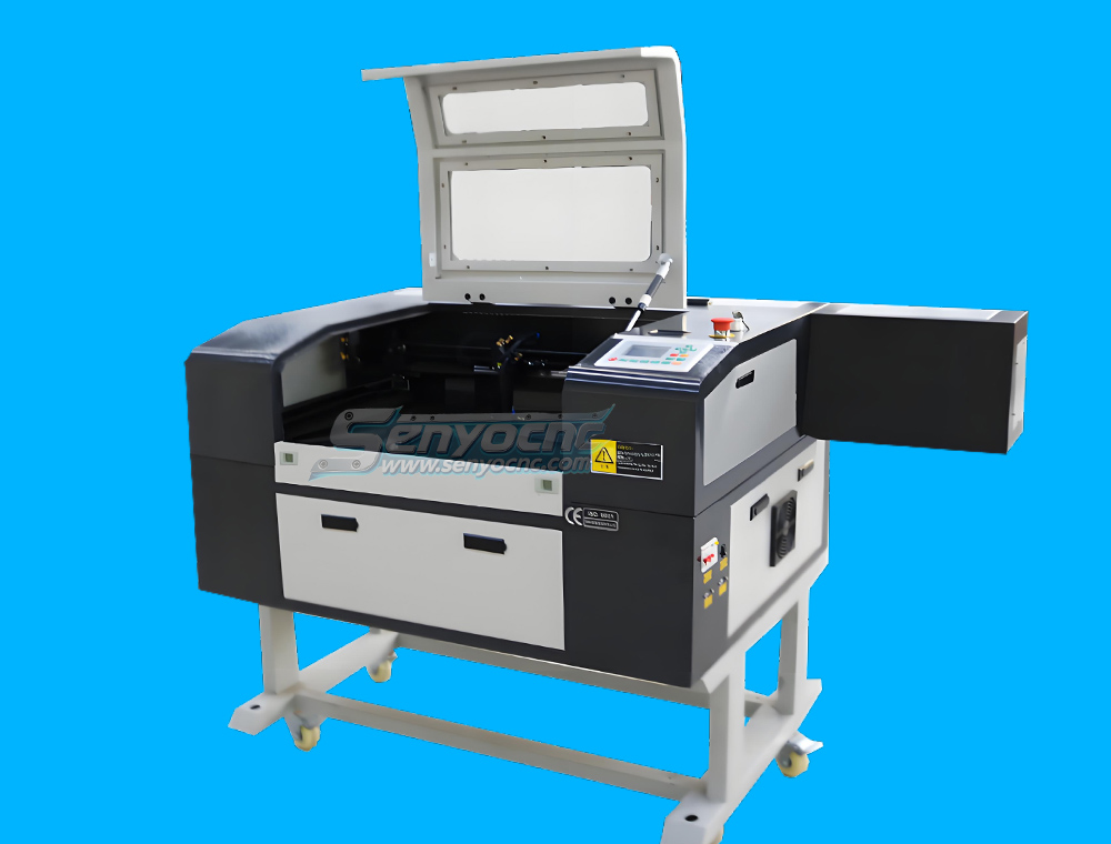
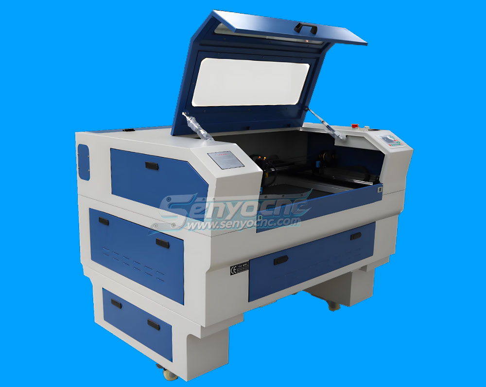
- How To Install & Setup CO2 Laser Engraving Cutting Machine?
- How to Install and Use NcStudio Controller & Software for CNC Router Machine?
- A guide to CNC Router Tools and CNC Router Bits
- How to buy a CNC machine?
Mini Desktop CNC Router for Gifts Making Small Business
Best Granite marble manual polishing machine For Sale
Stone Processing CNC Equipment Automatic Tool Changer CNC Quartz Stone Machining
3020 40W Mini CO2 Laser Engraving Cutting Machine
New Design Mini Stone CNC Machine for Marble, Granite and Quartz
Portable CNC Flame Cutting Machine with Plasma Torch for Sale
High-Precision Mini Hobby CNC Plasma Cutting Machine for Metal
Mini CNC Plasma Cutter With Rotary
4 Axis 1325 Sculpture Machine Cnc Carving Marble Granite Stone Cnc Router
Z Height 1000MM 4-AXIS Stone Engraving CNC Machine Heavy-duty Stone CNC Machine Stone Relief Carving CNC For Sale
4030 portable mini co2 laser carving and desktop rubber stamp laser engraving machine
Stone CNC Router For Kitchen sink tile carving and cutting Marble, Granite and Quartz
Robust CNC Plasma Cutting Machines with Flame Cut Head for Heavy-Duty Industrial Use
Small Portable CO₂ Laser Cutter Engraving for DIY & Business – Ideal for Wood, Acrylic, Leather
1325 3 Axis 4x8 CNC Stone Router for Sale
Mini CO2 Laser 5030 Cutting Engraving Machine For Sale
Portable CNC Plasma Flame Cutting Machine for Sale at Cost Price
Portable Cnc Plasma Oxyfuel Sheet Metal Cutting Machine for sale
CNC Plasma Cutters for Customized Metalwork –Rotary&Drilling Head
Small Table design 6040 Easy Move CO2 Hobby Laser Cutter Machine for Beginners
High-Efficiency 2 Heads CNC Machine for Aluminum Stone Marble Engraving & Cutting
Best CNC 2 Spindle 4-AXIS Stone Carving Machine High-precision Stone Carving Stone Countertop Fabrication
Top Rated 2x3 CO2 Hobby Laser Cutting Machine for Sale at Affordable Price
Best 4x8 CNC Plasma Cutter Table for Sale at Affordable Price
Entry Level CO2 Hobby Laser Cutter Machine for Beginners
Top CNC Plasma Cutters for Automotive, Aerospace, and Manufacturing Industries
Precision Stone Engraving Machines for Memorials & Signs
Portable Co2 9060 Laser Nonmetal Cutting Engraving Machine
1090 CO2 Laser Machine with Ruida Controller for Non-metal Glass Acrylic Engraving Cutting
Entry Level 9060 CO2 Hobby Laser Cutter Machine for Beginners
1325 Wood CNC Router DSP A11 Controller Wood Cutting In Test
Stone Edage Polish Machine In Test
1325 ATC Wood CNC Router Furniture MDF Cutting In Test
1 Hold 2 Spindle Stone With Rotary Marble Engraving Machine In Test
Muliti Head 3 spindle Mable Caving Machine In Work

CNC Parts In Delivery
Protable 1530 120A CNC Metal Cutting Machine With Flame Head Gas Cutting In Test
1000mm Wood CNC Polish Machine Shipping
1530 Fiber Metal Cutting 3000W In Test
20W Table Fiber Marking 4 Axis With Rotary In Test
Customzied High Z height 4th Axis Stone Marble Caving Machine 1225 Test
Buy 6090 Laser Cutting Machine For hobbyists startups Price Supplier
Mini Hobby 300X200 CO2 Laser Engraving & Cutting Machine Test
CNC Polish Machine 1000mm In Test
1325 Stone CNC Router Machine Kitchen Tank Working
1290 CNC Laser Nonmetal Cutting & Engraving Machine In Test
2 Spindle 2 Rotary 3D Marble Engraving Machine Work
1530 Stone caving Marble CNC Router Work
Multi Heads 8 Spindle Two Hold Wood CNC Router Machine In Test Work
50W Raycus Table Laser Marking Machine Test Work
5030 CO2 Laser Mini Hobby Machine In Test Work
Mini 6090- 3D Wood Engraving Work Test
1530 Plasma Metal Cutting Machine
1825 3D Wood CNC Router With Mach3 Controller and Dust Collect
Easy feeding Worktable Stone Marble engraving Machine SYS1530 In Test Work
CO2 wood plastic Cutting & Engraving Machine 1290 In Test Work
6090 Metal Engraving 4 axis Drilling PVC Tube Work Test
6090 Metal Aluminum Engraving Cutting Test Work
ATC 1325 Liner Tool changer Wood CNC Router In Test Work
50W JPT Fiber laser Table design With Rotary In test
The Apprentice Maze Puzzle Box
Box laser cutting software share
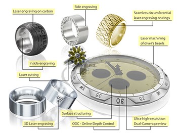
laser marking and engraving for the jewelry industry
Copper cutting for fiber laser cutting machine
Aluminum Cutting for fiber laser cutting machine
CS Laser Cutting Factors that Affect the Process
Stainless steel Fiber Laser Cutting
2d&3d wood MDF carving and cutting
3D CNC Router for Stone Relief Carving Projects
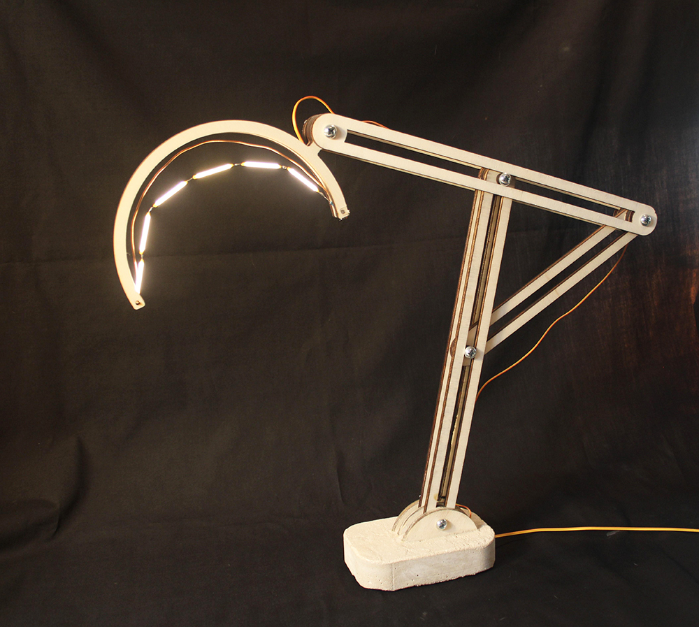
Laser Cut Adjustable Table Lamp
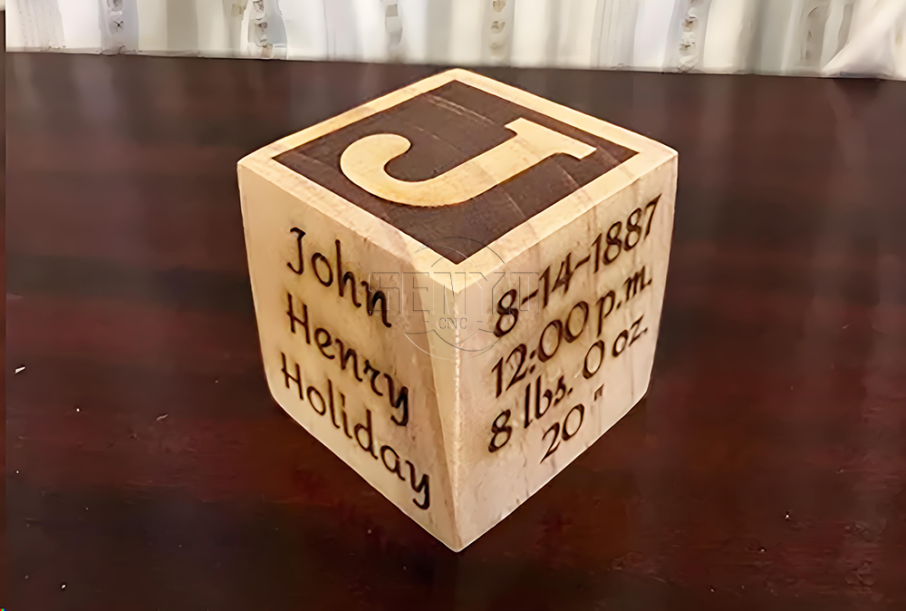
CO2 Laser cutting Baby Birth Block
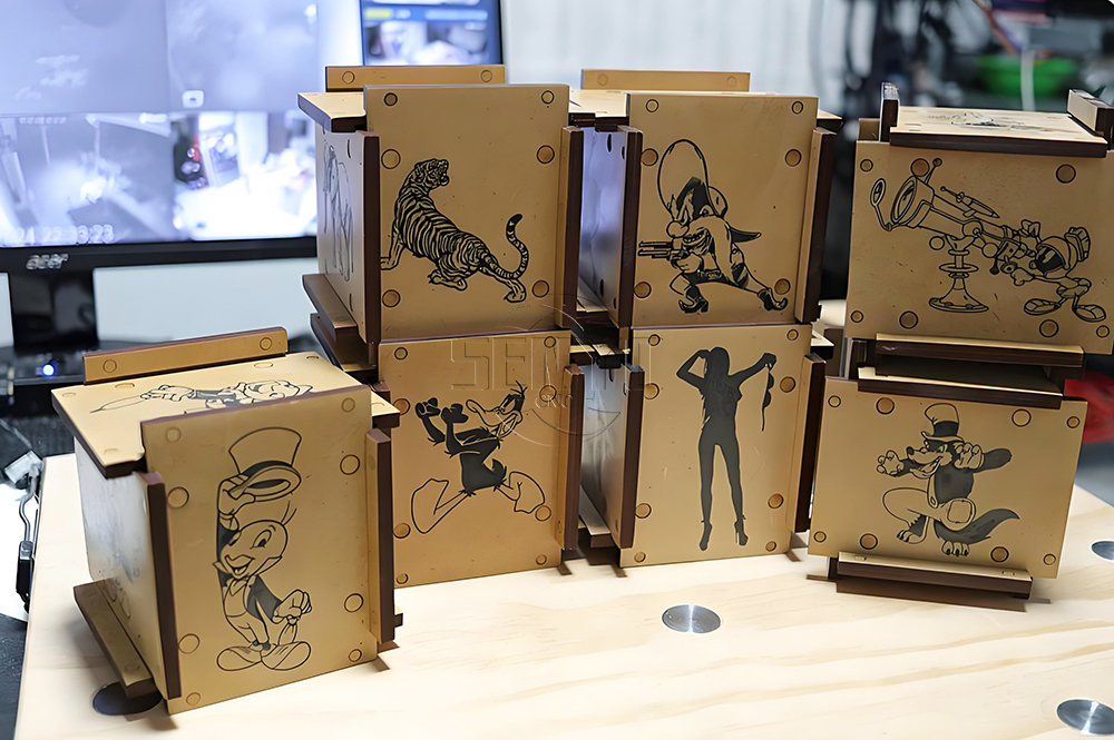
CO2 laser cutting and engraving for 6 Sided Box Puzzle
Co2 laser wood cut Illuminated Pattern Box
Engrave Round Parts With 50W Fiber Laser Marking Machine
CNC Plasma Cut Deer Head
Relief Map on a CNC Router
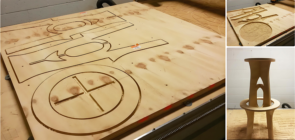
CNC Router Bar Stool
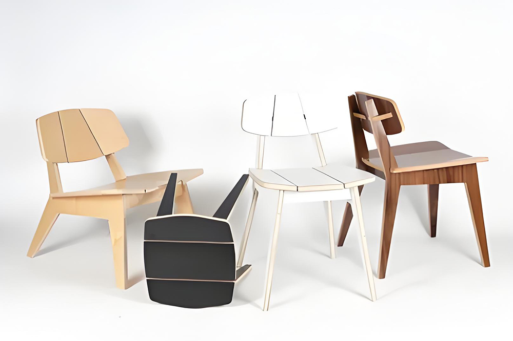
Wood Chair Made With CNC Router
Competitive Price New Design Waterjet Machine 3 axis Cutting Machine

Typical industries that use waterjet technology
What main benefits to waterjet cutting ?
DTF Printer Machine Application
Typical fields of application
UV Laser Marking Machine For Glasses Engraving

GOLD Engraving -Fiber laser marking work
Sover Engraving -Fiber metal engraving and marking
3D Marking Logo deep engraving -Fiber marking machine
MOPA Fiber Laser Marking Machine Application and Samples
Fiber Laser Engraving and Marking Machine for Metalworking Projects
Stone shaft Rotary use engrave cnc router machine
Jacob from United States
I am a beginner at CNC, I’ve never used a CNC machine before and with in a day I was carving. An awesome machine for a beginner to learn as hobbyists. I used the manual and the help video. One hour to assemble and test, very friendly and easy to use. It’s a good buy for the money. I would definitely recommend this machine to someone getting into CNCs.
Weinstein from France
I've been using CNC plasma SYP2060-300A and I am very impressed with this unit.
This unit is of higher quality, made in China. Five stars all the way!
Fiber Laser Marking Machine from Robert Evans 🇮🇪 Ireland
We bought the SYJF50W fiber laser marking machine for stainless steel and aluminum parts. The marking is sharp, permanent, and very fast. After several months of production, the machine continues to perform perfectly.”
ATC Wood CNC Router from Andrew Collins 🇳🇿 New Zealand
The SYM2040 automatic tool changer saves us a significant amount of production time. Tool changes are fast and accurate, and the machine performs complex woodworking jobs without any problems. Excellent machine and excellent service.
Stone CNC Router from Daniel Murphy🇦🇺 Australia
Our company produces granite and marble countertops. This SYS1530-R stone CNC router delivers precise carving and stable performance even during long working hours. The heavy-duty structure makes a noticeable difference compared to our previous machine.”
Plasma Cutting Machine from James Wilson 🇨🇦 Canada
The SYP2060 plasma cutting machine exceeded our expectations. It cuts mild steel quickly with smooth edges and very little slag. The controller is easy to learn, and the machine has been reliable since day one. Great value for money.”
CO₂ Laser Cutting & Engraving Machine from Michael Carter🇬🇧 United Kingdom
CO₂ Laser Cutting & Engraving MachineWe use the SYJ2030 CO₂ laser machine mainly for acrylic and MDF products. The engraving quality is clean, and the cutting edges require almost no finishing. SENYO provided complete operation videos and answered every question promptly.
Wood CNC Router Machine from David Thompson 🇺🇸 United States
We purchased the SYM1325ATC With Cutting Saw Wood CNC Router for cabinet production six months ago. The machine has been running every day with excellent stability. The cutting accuracy and edge quality are impressive, and the installation guidance from the SENYO team was very professional. We are very satisfied with our investment.
2040 from INDIAN
Best 2040 CNC Router Good Price and Quality ! Thank SENYOQC
10w uv laser from American
Best supplier ! I bought 3 machines for laser and router , thank you Aillen ! --Alec


 manager@senyocnc.com
 SENYOCNC
 +86 1525 3141 880
 +86 1525 3141 880
 2061579344
