

Layout Design of a Furniture Prodtction Line Using Formal Method
From: 本站 Date: 31st August 2021 Author: shengangtong Views: 1868
Journal of Industrial and Systems Engineering
Vol. 1, No.1, pp81-96
Spring 2007
Layout Design of a Furniture Production Line Using Formal Methods
Pinto Wilsten J, Shayan E. *
Faculty of Engineering, Swinbume University of Technology, Hawthom, Victoria, Australia
ABSTRACT
This paper experiments application of different heuristic approaches to a real facility layout problem at a furniture
manufacturing company. All the models are compared using AHP, where a number of parameters of interest are
employed. The experiment shows that formal layout modelling approaches can be effectively used real problems
faced in industry, leading to significant improvements.
Keywords: Facilities layout design, Layout algorithms, Optimisation, Production lines.
1. INTRODUCTION
The fumniture industry is experiencing a very competitive era like many others, thus striving hard to find methods to
reduce manufacturing costs, improve quality etc. As part of a productivity improvement program in a manufacturing
company herein called (The Company = TC) we conducted a project to optimize the layout design of the production
line at the shop floor of this company aiming at overcoming the current problems attributed to the inefficient layout. It
was decided to apply a number of layout modelling techniques to generate a near optimal layout based on formal
methods that are rarely used in practice. The modelling techniques used are Graph Theory, Bloc Plan, CRAFT,
Optimum Sequence and Genetic Algorithm. These layouts were then evaluated and compared using three criteria
namely Total Area, Flow * Dist and the Adjacency Percentage. Total Area refers to the area occupied by the
production line for each model developed. Flow * Dist calculates the sum of products of the flow and the distance
between every two facilities. Adjacency Percentage calculates the percentage of the facilities that meet the
requirement of being adjacent.
Selection of the best layout was also done formally usingmulti-criteriadecision making approach AHP (Satty, 1980)
using Expert Choice software. The best layout was compared with the existing layout to demonstrate improvements
gained by formal approaches to layout design.
The definition of a plant layout problem is to find the best arrangement of physical facilities to provide an efficient
operation (Hassan and Hogg, 1991). The layout affects the cost of material handling, lead time and throughput. It
hence affects the overall productivity and efficiency of the plant. According to Tompkins and White (1984) the design
of facilities has been around throughout recorded history and indeed town facilities that were designed and built are
described in the ancient
* Corresponding Author
history of Greece and the Roman Empire. Among the first who studied this problem are Amour and Buffa et al.
(1964). Little seems to have been published in the 1950's. Francis and White (1974) were the first who collected
and updated the early research on this area. Later research has been updated by two studies the first by Domschke
and Drexl (1985) and the other by Francis et al. (1992). Hassan and Hogg (1991) reported an extensive study on
the type of data required in the machine layout problem. The machine layout data is considered in a hierarchy;
depending on how detailed the layout is designed. When the layout required is only to find the relative arrangement
of machines, data representing machine number and their flow relationships are sufficient. However, if a detailed
layout is needed, more data is required. In finding data some difculties may arise especially in new manufacturing
facilities where the data is not yet available. Whenthe layout is developed for modern and automated facilities, the
required data cannot be obtained from historical data or from similar facilities since they may not exist.
Mathematical modelling has been suggested as a way to get an optimal solution for the facility layout problem.
Since the first mathematical model developed by Koopmans and Beckmann (1957) as a quadratic assignment
problem, interest in the area has attracted considerable growth. This opened up a new and interesting field for the
researcher. In searching for a solution to the facility layout problem, researchers launched themselves into
developing mathematical models. Houshyar and White (1993) looked at layout problem as
aninteger-programmingmodel while Rosenblatt (1986) formulated the layout problem as a dynamic programming
model. Palekar et al. (1992) deal with uncertainty and Shang (1993) uses amulti-criteriaapproach. On the other
hand, Leung (1992) presented a graph theory formulation.
Green andAl-Hakim(1985) used a GA to find the part family as well as the layout between cells. In his formulation,
he limited the arrangement of cell as either linear single row or linear double row. The developed algorithm is more
towards the cells system layout, or the layout of production floor, rather than the cell layout, or the machine layout.
The actual layout of machines within cells was not considered. Banerjee and Zhou (1995) formulated the facilitis
design optimization problem for asingle-looplayout using genetic algorithms. The developed algorithm is for the cell
systems layout and hence does not consider the layout of machines within cell. Fu and Kaku (1997) presented a
plant layout problem formulation for a job shop manufacturing system where the objective is to minimize the
average Work in Process. They modeled the plant as an open queuing network under a set of assumptions. The
problem reduces to a Queuing Assignment Problem (QAP). Simulation was used to minimize the average Material
Handling costs and minimizing the Average Work in Process.
2. MODELING APPROACHES
Models are categorised depending on their nature, assumptions and objectives. The first generic Systematic L ayout
Planning approach, developed by Muthor (1955), is still a useful scheme specially if supported by other approaches
and assisted by computer. Construction approaches, Hassan and Hogg (1991) for example, build a layout from
scratch while Improvement Methods, Bozer, Meller and Erlebacher (1994) for example, attempt to modify an
existing layout for better results. Optimising methods and also heuristics for layout by is well documented by Heragu
(2007).De-Alvarengaand Gomes (2000) discuss ameta-heuristicapproach as a way to overcome the NP- hard
nature of optimal models.
The various modelling techniques used in this work are Graph Theory, CRAFT, Optimum Sequence, BL _OCPL AN
and Genetic Algorithm. Explained below are parameters that are required by each algorithm in order to model the
same.
Graph Theory
Graph theory (Foulds and Robinson, 1976; Giffin et al., 1984; Kim and Kim, 1985; and Leung,
1992)applies an edge–weight maximal planar graph in which the vertices (V) represents the
facilities and the edges (E) represent adjacencies and Kn denotes the complete graph of n Vertices.
Given a weighted graph G, the facility layout problem is to find a maximum weighted spanning
sub-graph G’ of G that is planar.
This paper uses 2 different kinds of approaches to model the case study. The first approach is the
Delta-hedron method by Foulds and Robinson (1976). The method involves simple insertion with
an initial K4, and vertices are then inserted one by one according to a benefit criterion. The second
approach used is the wheel expansion algorithm (Green and Al-Hakim, 1985). Here the initial K4 is
obtained by selecting an edge having the highest weight and then applying two successive vertex
insertion according to the benefit criteria. The algorithm then proceeds with an insertion process,
called the wheel expansion procedure. A wheel on n vertices is defined as a cycle on (n-1) vertices
(termed the rim), such that each vertex is adjacent to one additional vertex (termed the hub). Let W
be a wheel having the hub x. Select two vertices k and l, which are the rims of this cycle. A vertex y
from the set of unused vertices is then inserted to this wheel in the current partial sub-graph such
that y is a hub of the new wheel W′ containing k, l and x as its rims, and all rims in W are now
adjacent to vertex x or vertex y. By inserting each unused vertex successively in the above fashion,
the final maximal planar sub graph is obtained.
Using CRAFT
CRAFT (Computerized Relative Allocation of Facilities Technique) uses a pair wise exchange to
develop a layout (Buffa et al., 1964; Hicks and Lowan, 1976). CRAFT does not examine all
possible pair wise exchange before generating an improved layout. The input data includes
dimensions of the building and facilities, flow of material or frequency of trips between facility
pairs and cost per unit load per unit distance. The product of the flow (f) and distance (d) provides
the cost of moving materials between 2 facilities. The cost reduction is then calculated based on the
pre and post exchange material handling cost contribution.
Optimum Sequence
The method of solution starts with an arbitrary sequential layout and tries to improve it by switching
two departments in the sequence (Heragu, 1997). At each step, the method computes the
flow*distance changes for all possible switches of two departments and chooses the most effective
pair. The two departments are switched and the method repeats. The process stops when no switch
results in a reduced cost. The input required to generate a layout using Optimum Sequence are
mainly dimensions of the building and facilities, the flow of material or frequency of trips between
facility pairs and cost per unit load per unit distance.
Using BLOCPLAN
BLOCPLAN is an interactive program used to develop and improve both single and multi storey
layout (Green and Al-Hakim, 1985). It is a simple program which generates good initial layouts due
to its flexibility based on several imbedded options. It uses both quantitative and qualitative data to 84
Pinto and Shayan generate several block layouts and their measure of fitness.
The user can choose the relative solutions based on circumstances.
Genetic Algorithm
There are numerous ways of formulating facilities Layout problems through genetic
algorithms(GA). Banerjee, Zhou, and Montreuil(1997) applied GA to cell layout.. Slicing
tree structure was first suggested by Otten (1982) as a way to represent a class of layouts. The
approach was later used by many authors including Tam and Chan (1995) who used it to solve
the unequal area layout problem with geometric constraints. The GA algorithm used in this
work was developed by Shayan and Chittilappilli (2004) based on slicing tree structures (STC). It
codes a tree structured candidate layout into a special structure of 2 dimensional chromosomes
which shows the relative location of each facility in a slicing tree. Special schemes are available to
manipulate the chromosome in GA operations (Tam and Li, 1991). A new “cloning” operation was
also introduced in Shayan and Al-Hakim (1999). The chosen solution through GA is then
converted to a slicing layout. It starts with one initial block that contains all the facilities. As the
layout constructing algorithm progresses, new partitions are made and facilities are assigned
between newly generated blocks, until there is only one facility in each block. Meanwhile the
coordinates of each facility is also calculated. Rectilinear distance between centroids of facilities is
used to evaluate the fitness of the respective chromosome. When the GA terminates, a drawing
procedure takes over to print the layout using the stored values of the coordinates. The objective
function has a penalty term to avoid narrow slices.
3. EXPERIMENTATION VIA A CASE STUDY
To test the performance of the methods described before, they were all applied to a real case
scenario in furniture manufacturing. The Company manufactures 9 different styles of Chairs, 2-
Seaters and 3-Seaters respectively. Production of all the styles follows the same set of operations
but involve different raw materials. 5 parts namely Seat cushions, Back cushions, Arms Seats and
Backs are produced internally in batches of varied sizes, in scattered areas (departments).
Movement of parts generates problems such as work in progress, missing parts, shortages,
congestion and wrong placement.
Each product goes through 11 operations which begin at Facility 1 – Cutting Area and end at
Facility 11- Bolt up Area. Each of the final assembly can be broken down into subassemblies
named the same. These subassemblies meet up at the Bolt -Up Facility for final assembly. Each of
the subassemblies begin their operations independently and all go through a fixed set of operations
which is shown in the form of an assembly chart in Fig 1. The facilities of the current layout are not
placed according to the sequence of operations.
Due to this there is no sequential flow of materials, giving rise to work in progress. The interaction
between facilities can be determined using subjective as well as objective measures. The main input
required for flow charts is the demand, the quantity of materials produced and the amount of
material that flows between each machine. The flow of material is calculated based on amount of
flow of material traveling per 10 months * Unit of measure which is shown in Figure 2. Figure 3
shows the area of each of the department used in the case study. Figure 4 shows the current layout
of the Case Study.


4. APPLICATION OF THE MODELING APPROACHES
Here the various modelling approaches discussed in section 2 are applied to the case study to
generate alternative layouts for comparison.
4.1 Using Graph Theory
Table 1 shows the comparison of the results using two different approaches of Graph Theory
namely the Foulds and Robinsons method and the Wheels and Rims method. Table 1 it clearly
shows that the Foulds and the Robinsons method is the better of the two results. The results of the
Foulds and Robinsons method are explained in detail in Figures 5-7.


4.2 Using CRAFT
The input data for CRAFT is entered and the initial cost for the current layout is first calculated.
This cost can be reduced using a pair wise comparison as shown in Figures 8,9.


The results obtained by CRAFT are shown in Table 2. Based on the above calculations a new and
improved layout can be drawn which is shown in Figure 10

4.3 Optimum Sequence Algorithm
The input data is the same as for CRAFT except that it follows a different set of pair wise
comparison. Table 3 shows the results drawn from the improved layout. Figure 11 shows the
improved layout using Optimum Sequence.


4.4 Using BLOCPLAN
The Flow matrix chart was converted to a REL chart as shown in Figure 12 with the following
parameters:

Table 4 shows the results using different kinds of approach. As seen the BLOCPLAN using an
automated search showed better results than using the Construction Algorithm.

4.5 Using Genetic Algorithm
The best solution found by the algorithm is shown in Figure 14. This is then converted to the layout
in Figure 15 for common comparisons with other models.


Table 5 shows the results using Genetic Algorithm.

5. COMPARISONS OF EXPERIMENTATION RESULTS BY AHP
Table 6 summarizes the results obtained from all the modelling techniques versus the Current
Layout for comparison. Section of the best layout will be done based on three factors namely Total
Area (Minimze), Flow * Distance (Maximize) and the Adjacency percentage (Maximize). The main
objective is to reduce the WIP and organise a systematic flow of materials. As a result the flow *
distance matrix is the most important parameter.
Table 6 Summary of results using all modelling techniques versus the results of the current layout

Table 7 shows the mix ranking of the alternative layouts based on various factors. For example
Layout 1 has a poor rank in Area and F*D while is the best in Adjacency. The combination makes it
difficult to choose one over the others. We urge to use a formal technique, AHP, implemented by
Expert Choice software

AHPcompares the relative importance of each pair of children with respect to the parent. Once the
pair comparisons is completed, the approach synthesis the results using some mathematical models
to determine an overall ranking. Figure 16 shows the ranking of the results achieved from all
algorithms with respect the goal of best choice solution.

The best solution is achieved by BLOCPLAN ( Automated Search) followed by Graph Theory
using Foulds and Robinsons Method, then Genetic Algorithm. The other solutions are far worse.
Note that due to the inherent subjectivities ranking is not an absolute indication of better choice,
rather it is a recommendation that the user can entertain to suit the needs. 94
We propose the layout generated using BLOCPLAN using Automated Search to be the chosen
solution. When this was decided a sensitivity analysis was conducted to ensure that the choice is
robust. If time allows this should be done for other close alternatives before the choice is made.
6. CONCLUSIONS
The goal in this paper was to use various modelling techniques to select the best layout for a
furniture company. The best layout was generated by BLOCPLAN using Automated Search as figure 17.

Table 9 shows the improvements of the proposed solution over the current layout. Note that the
layout shows the blocks and their relative locations. Practical limitations need to be applied to suit
all the needs. Then further details of each block can be planned, if necessary in the same manner.
Table 9: Improvements over the current layout using modeling techniques

The result was quite satisfactory to the company, which did not have any knowledge of the
scientific approaches.
REFERENCES
[1] Banerjee P., Zhou Y. (1995), Facilities layout design optimization with single loop material flow
path configuration; Int. Journal of Production Research 33(1); 183-204.
[2] Banerjee P., Zhou Y., Montreuil B. (1997),Genetically assisted optimization of cell layout and
material flow path skeleton; IIE Trans 29(4); 277-292. Layout Design of a Furniture... 95
[3] Bozer Y.A, Meller R.D., Erlebacher S.J. (1994), An improvement type layout algorithm;
International Journal of Production Research 1; 1675-1692.
[4] Buffa E.S., Armour G.C., Vollman T.E. (1964), Allocating facilities with CRAFT; Harvard Business
Review 42; 136-159.
[5] De-Alvarenga A.G., Gomes N.J., Mestria M. (2000), Metaheuristic methods for a class of the facility
layout problems; Journal of Intelligent Manufacturing 11; 421-430.
[6] Domschke W., Drexl A. (1985), Location and layout planning, An international bibliography;
Springer Verlag, Berlin.
[7] Foulds L.R., Robinson D.F. (1976), A strategy for solving the plant layout problem; Operational
Research Quarterly 27; 845-855.
[8] Francis R.L., McGinnis Jr. L.F., White J.A. (1992), 2nd Ed, Facility layout and location, An
analytical approach; Prentice Hall; Englewood Cliffs, NJ.
[9] Fu M.C., Kaku B.K. (1997), Minimizing work in progress and material handling in the facilities
layout problem; IIE Trans 29; 29-36.
[10] Giffin J.W., Foulds L.R. Cameron D.C. (1984), Drawing a block plan from a REL chart with graph
theory and microcomputer; Computers & Industrial Engineering 10; 109-116.
[11] Green R.H., Al-Hakim L. (1985), A heuristic for facilities layout planning; OMEGA, International
Journal of Management Science 13; 469-474.
[12] Hassan M.M.D., Hogg G.L. (1991), On constructing a block layout by graph theory;
International Journal of Production Research 29; 1263-1278.
[13] Heragu S.S. (2007), 2nd Ed, Facilities Design; iUniverse Inc., NY.
[14] Hicks P.E., Lowan T.E. (1976), CRAFT-M for layout re-arrangement; Industrial Engineering 8(5);
30-35.
[15] Houshyar A., White B. (1993), Exact optimal solution for facility layout – deciding which pairs of
locations should be adjacent; Computers and Industrial Engineering 24(2); 287-290.
[16] Kim J.Y., Kim Y.D. (1985), Graphic theoretic for unequal sized facility layout problems; OMEGA,
International Journal of Management Science 23; 391-401.
[17] Koopmans T.C., Beckmann M. (1957), Assignment problems and the location of Economic
Activities; Econometrica 25(1), 53-76.
[18] Leung J.A. (1992), A new graph theoretic heuristic for facility layout, Management Science 38; 554-
605.
[19] Meller R.D., Narayanan V., Vance P.H. (1998), Optimal facility layout design; Operation Research
Letters 23;117-127.
[20] Muther R. (1955), Practical plant layout; McGraw-Hill; New York, NY.
[21] Otten R.H.J.M. (1982), Automatic floor plan design; Proceedings of the 19th ACM-IEEE
DesignAutomation Conference; 261-267. 96
[22] Palekar V.S., Batta R., Bosch R.M., Elhence S. (1992), Modeling uncertainties in plant layout
problems; European Journal of Operations Research 63(2); 347-359.
[23] Rosenblatt M.J. (1986), The dynamics of plant layout; Management Science 32(1); 76-86.
[24] Satty T.L. (1980), Analytical hierarchic process; McGraw Hill; New York.
[25] Shang J.S. (1993), Multicriteria facility layout problem -An integrated approach; European Journal
of Operational Research; 66(3); 291-304 .
[26] Shayan E., Al-Hakim L., 1999. "Cloning in layout design problem: A genetic algorithm approach."
Proceedings of the 15th International Conference on Production Research; Hillery, M., Lewis, H.
Eds.), University of Limerick, Ireland; 787-792.
[27] Shayan E., Chittilappilly A.(2004) , Genetic algorithm for facilities layout problems based on slicing
tree structure; Int. J Production Research; 42(19); 4055–4067.
[28] Tam K.Y., Chan S.K. (1998), Solving facility layout problems with geometric constraints using
parallel genetic algorithms: experimentation and findings; International Journal of Production
Research 36(12); 3411-3423.
[29] Tam K.Y., Li S.L. (1991), A hierarchal approach to facility layout problem; International Journal
Production Research, 29; 165-184.
[30] Tompkins J.A., White J.A. (1984), Facilities planning; John Wiley & Sons, NY.
![]() Layout Design of a Furniture Prodtction Line Using Formal Method.pdf
Layout Design of a Furniture Prodtction Line Using Formal Method.pdf


• Previous: A practical guide for beginners to set up, debug and use the plasma cutting machine
• Next: How choose a suitable Panel furniture production line ?
Mini Desktop CNC Router for Gifts Making Small Business
Best Granite marble manual polishing machine For Sale
Stone Processing CNC Equipment Automatic Tool Changer CNC Quartz Stone Machining
3020 40W Mini CO2 Laser Engraving Cutting Machine
New Design Mini Stone CNC Machine for Marble, Granite and Quartz
Portable CNC Flame Cutting Machine with Plasma Torch for Sale
High-Precision Mini Hobby CNC Plasma Cutting Machine for Metal
Mini CNC Plasma Cutter With Rotary
4 Axis 1325 Sculpture Machine Cnc Carving Marble Granite Stone Cnc Router
Z Height 1000MM 4-AXIS Stone Engraving CNC Machine Heavy-duty Stone CNC Machine Stone Relief Carving CNC For Sale
4030 portable mini co2 laser carving and desktop rubber stamp laser engraving machine
Stone CNC Router For Kitchen sink tile carving and cutting Marble, Granite and Quartz
Robust CNC Plasma Cutting Machines with Flame Cut Head for Heavy-Duty Industrial Use
Small Portable CO₂ Laser Cutter Engraving for DIY & Business – Ideal for Wood, Acrylic, Leather
1325 3 Axis 4x8 CNC Stone Router for Sale
Mini CO2 Laser 5030 Cutting Engraving Machine For Sale
Portable CNC Plasma Flame Cutting Machine for Sale at Cost Price
Portable Cnc Plasma Oxyfuel Sheet Metal Cutting Machine for sale
CNC Plasma Cutters for Customized Metalwork –Rotary&Drilling Head
Small Table design 6040 Easy Move CO2 Hobby Laser Cutter Machine for Beginners
High-Efficiency 2 Heads CNC Machine for Aluminum Stone Marble Engraving & Cutting
Best CNC 2 Spindle 4-AXIS Stone Carving Machine High-precision Stone Carving Stone Countertop Fabrication
Top Rated 2x3 CO2 Hobby Laser Cutting Machine for Sale at Affordable Price
Best 4x8 CNC Plasma Cutter Table for Sale at Affordable Price
Entry Level CO2 Hobby Laser Cutter Machine for Beginners
Top CNC Plasma Cutters for Automotive, Aerospace, and Manufacturing Industries
Precision Stone Engraving Machines for Memorials & Signs
Portable Co2 9060 Laser Nonmetal Cutting Engraving Machine
1090 CO2 Laser Machine with Ruida Controller for Non-metal Glass Acrylic Engraving Cutting
Entry Level 9060 CO2 Hobby Laser Cutter Machine for Beginners
1325 Wood CNC Router DSP A11 Controller Wood Cutting In Test
Stone Edage Polish Machine In Test
1325 ATC Wood CNC Router Furniture MDF Cutting In Test
1 Hold 2 Spindle Stone With Rotary Marble Engraving Machine In Test
Muliti Head 3 spindle Mable Caving Machine In Work

CNC Parts In Delivery
Protable 1530 120A CNC Metal Cutting Machine With Flame Head Gas Cutting In Test
1000mm Wood CNC Polish Machine Shipping
1530 Fiber Metal Cutting 3000W In Test
20W Table Fiber Marking 4 Axis With Rotary In Test
Customzied High Z height 4th Axis Stone Marble Caving Machine 1225 Test
Buy 6090 Laser Cutting Machine For hobbyists startups Price Supplier
Mini Hobby 300X200 CO2 Laser Engraving & Cutting Machine Test
CNC Polish Machine 1000mm In Test
1325 Stone CNC Router Machine Kitchen Tank Working
1290 CNC Laser Nonmetal Cutting & Engraving Machine In Test
2 Spindle 2 Rotary 3D Marble Engraving Machine Work
1530 Stone caving Marble CNC Router Work
Multi Heads 8 Spindle Two Hold Wood CNC Router Machine In Test Work
50W Raycus Table Laser Marking Machine Test Work
5030 CO2 Laser Mini Hobby Machine In Test Work
Mini 6090- 3D Wood Engraving Work Test
1530 Plasma Metal Cutting Machine
1825 3D Wood CNC Router With Mach3 Controller and Dust Collect
Easy feeding Worktable Stone Marble engraving Machine SYS1530 In Test Work
CO2 wood plastic Cutting & Engraving Machine 1290 In Test Work
6090 Metal Engraving 4 axis Drilling PVC Tube Work Test
6090 Metal Aluminum Engraving Cutting Test Work
ATC 1325 Liner Tool changer Wood CNC Router In Test Work
50W JPT Fiber laser Table design With Rotary In test
The Apprentice Maze Puzzle Box
Box laser cutting software share
laser marking and engraving for the jewelry industry
Copper cutting for fiber laser cutting machine
Aluminum Cutting for fiber laser cutting machine
CS Laser Cutting Factors that Affect the Process
Stainless steel Fiber Laser Cutting
2d&3d wood MDF carving and cutting
3D CNC Router for Stone Relief Carving Projects
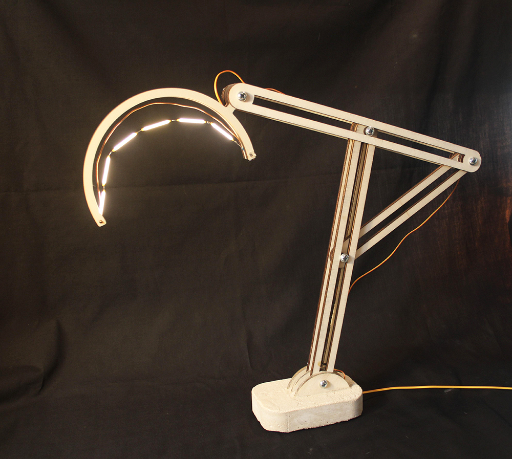
Laser Cut Adjustable Table Lamp
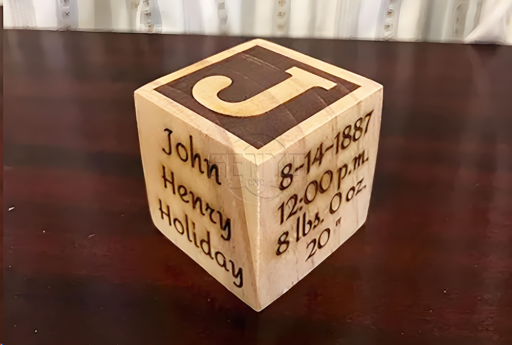
CO2 Laser cutting Baby Birth Block
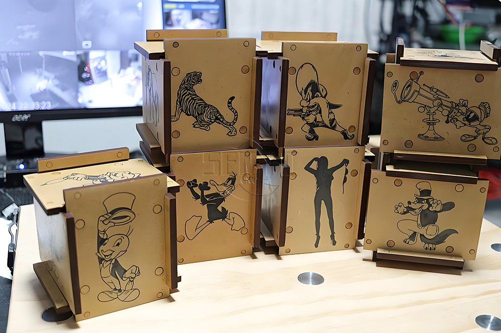
CO2 laser cutting and engraving for 6 Sided Box Puzzle
Co2 laser wood cut Illuminated Pattern Box
Engrave Round Parts With 50W Fiber Laser Marking Machine
CNC Plasma Cut Deer Head
Relief Map on a CNC Router
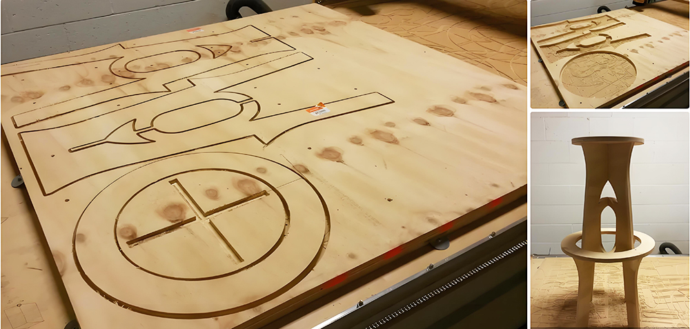
CNC Router Bar Stool
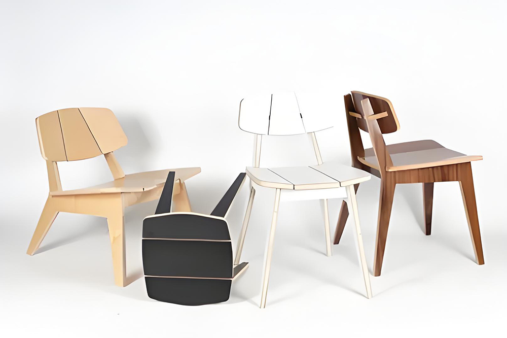
Wood Chair Made With CNC Router
Competitive Price New Design Waterjet Machine 3 axis Cutting Machine

Typical industries that use waterjet technology
What main benefits to waterjet cutting ?
DTF Printer Machine Application
Typical fields of application
UV Laser Marking Machine For Glasses Engraving

GOLD Engraving -Fiber laser marking work
Sover Engraving -Fiber metal engraving and marking
3D Marking Logo deep engraving -Fiber marking machine
MOPA Fiber Laser Marking Machine Application and Samples

Fiber Laser Engraving and Marking Machine for Metalworking Projects
Stone shaft Rotary use engrave cnc router machine
Jacob from United States
I am a beginner at CNC, I’ve never used a CNC machine before and with in a day I was carving. An awesome machine for a beginner to learn as hobbyists. I used the manual and the help video. One hour to assemble and test, very friendly and easy to use. It’s a good buy for the money. I would definitely recommend this machine to someone getting into CNCs.
Weinstein from France
I've been using CNC plasma SYP2060-300A and I am very impressed with this unit.
This unit is of higher quality, made in China. Five stars all the way!
Fiber Laser Marking Machine from Robert Evans 🇮🇪 Ireland
We bought the SYJF50W fiber laser marking machine for stainless steel and aluminum parts. The marking is sharp, permanent, and very fast. After several months of production, the machine continues to perform perfectly.”
ATC Wood CNC Router from Andrew Collins 🇳🇿 New Zealand
The SYM2040 automatic tool changer saves us a significant amount of production time. Tool changes are fast and accurate, and the machine performs complex woodworking jobs without any problems. Excellent machine and excellent service.
Stone CNC Router from Daniel Murphy🇦🇺 Australia
Our company produces granite and marble countertops. This SYS1530-R stone CNC router delivers precise carving and stable performance even during long working hours. The heavy-duty structure makes a noticeable difference compared to our previous machine.”
Plasma Cutting Machine from James Wilson 🇨🇦 Canada
The SYP2060 plasma cutting machine exceeded our expectations. It cuts mild steel quickly with smooth edges and very little slag. The controller is easy to learn, and the machine has been reliable since day one. Great value for money.”
CO₂ Laser Cutting & Engraving Machine from Michael Carter🇬🇧 United Kingdom
CO₂ Laser Cutting & Engraving MachineWe use the SYJ2030 CO₂ laser machine mainly for acrylic and MDF products. The engraving quality is clean, and the cutting edges require almost no finishing. SENYO provided complete operation videos and answered every question promptly.
Wood CNC Router Machine from David Thompson 🇺🇸 United States
We purchased the SYM1325ATC With Cutting Saw Wood CNC Router for cabinet production six months ago. The machine has been running every day with excellent stability. The cutting accuracy and edge quality are impressive, and the installation guidance from the SENYO team was very professional. We are very satisfied with our investment.
2040 from INDIAN
Best 2040 CNC Router Good Price and Quality ! Thank SENYOQC
10w uv laser from American
Best supplier ! I bought 3 machines for laser and router , thank you Aillen ! --Alec


 manager@senyocnc.com
 SENYOCNC
 +86 1525 3141 880
 +86 1525 3141 880
 2061579344
